Giant bicycles images upload uk general 2001 AC Page 9

- Pag. 9. -
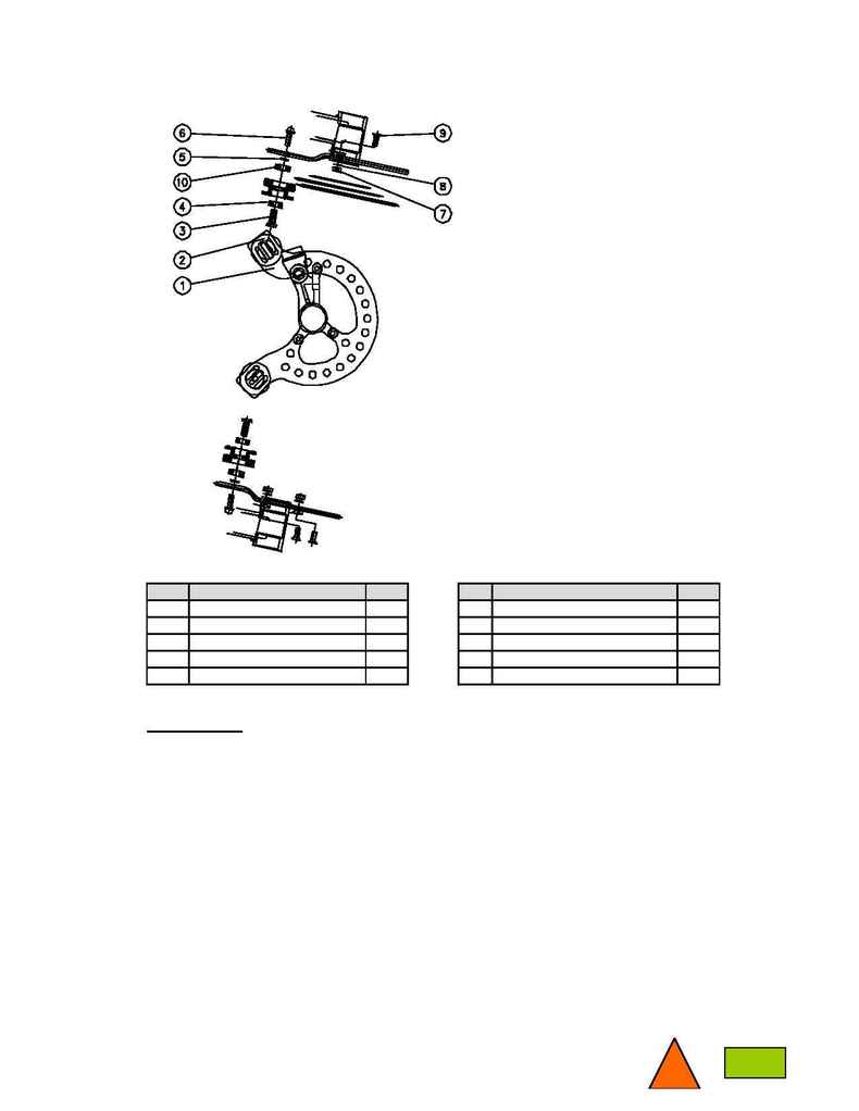
4. Chain tension device.
Nr.
Description
Qty.
Nr. Description
Qty.
1
Body
1
6
Bolt M6x20 mm.
2
2
Roller
2
7
Nut M6
3
3
Shaft
2
8
Washer M6
3
4
Roller bearing 6x19 mm.
2
9
Taper bolt M6x15 mm.
3
5
Washer M8
2
10 Roller bearing 7x22 mm.
2
4-1. Assembly.
The AC chain tension device is designed to be easily installed and removed to/from the frame. It can
be installed with all 3 chain rings (chain on the largest ring) or a single chain ring on the crank arm.
To insure proper chain and (rear) shifting function, keep the chain line at 57mm.
Installation:
1. Insert the taper bolt (9) through the bottom bracket shell mount and body (1). The bolt must come
in from the non-drive (LH) side.
2. Install washer (5) and nut (10) and tighten firmly.
3. Repeat step 1 and 2 for additional bolt assemblies.
4. With the chain in the largest sprocket on the rear cassette, the upper roller's groove should just rub
the top of the chain.
5. The lower roller's groove should have the chain wrap smoothly around it after exiting the
chain wheel (about 7 o'clock position).
6. Do not put any tension on the top of the chain, the bottom roller will supply the chain tension.
The top roller serves only as a guide.
Warning! Rollers need to be tightened on both sides simultaneously before each use.
Check and adjust all hardware.
Figure 5.
