Galil Motion Control cadman Page 4

Step 1:
Draw the Motion Path
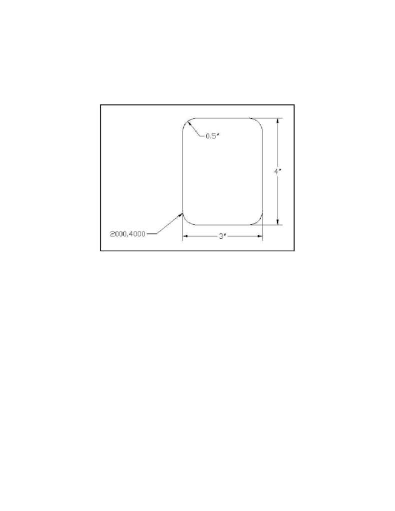
Figure 2 shows the desired adhesive contour drawn in CAD. Dimensions are shown for
demonstration purposes only and should not be included in any drawing to be translated.
Figure 2:
CAD drawing of desired motion path
Step 2:
Specify FIRST, LAST and SCALE directives
FIRST and LAST are placed as shown in Figure 3. FIRST is placed adjacent to the point
labeled (2000,4000) in Figure 2. LAST is placed above FIRST and is also associated with the
same point (for more information on association, refer to Section 2.2 Association Principles).
This causes the motion to follow a counter-clockwise path.
SCALE is specified as 1000 encoder counts per inch for each axis.
Step 3:
Specify mode of motion
Since a constant feed rate is desired, SMOOTH_MODE should be used. SMOOTH_MODE
causes all motion to be generated as a continuous, constant velocity path. SMOOTH_MODE is
the default setting for CAD-to-DMC and does not need to be explicitly specified in this case.
Step 4:
Add macros for system initialization and ON/OFF control of dispenser
FIRST_MACRO is executed before the actual motion path takes place. In this application, the
X and Y axes are homed and then brought to coordinates (2000,4000) for the beginning of
dispensing. Finally, a bit is set which turns on the dispenser. LAST_MACRO is executed after
the motion path has been completed. Figure 3 shows the implementation of these two macros.
