Galil Motion Control cadman Page 3

2. Run CAD->Cadtodmc.exe from the CD-ROM.
3. Enter password for installation. This should have been provided when the software was
purchased.
4. The InstallShield Wizard will guide you through the rest of the installation.
1.3 Basic Requirements
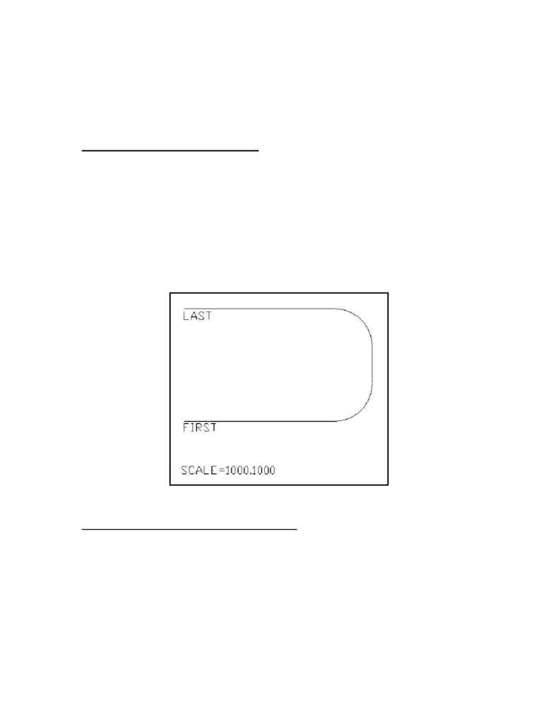
Figure 1 shows a sample CAD drawing which satisfies the minimum requirements for a
successful CAD-to-DMC file conversion. Every CAD drawing must contain each of the
following text directives:
Directive:
Description:
SCALE=m,n Relates encoder counts to user units for x and y axes
FIRST
Defines beginning of motion path
LAST
Defines end of motion path
(For full descriptions of these and other commands, please refer to Section 2.4 Command
Reference.)
Figure 1:
A valid CAD-to-DMC drawing
1.4 A Step-by-Step Example
This section takes you though the entire process of creating a motion control program from a
CAD drawing. The example demonstrates the basic requirements of the CAD-to-DMC
program, as well as more advanced features such as the use of macros.
Suppose you wish to apply adhesive to a part which is located on a stationary platform. The
adhesive applicator moves with respect to the stationary part. The adhesive must be dispensed
at a constant feed rate beginning at count coordinates (2000,4000). The dispenser should travel
in the counter-clockwise direction around the desired path.
