Brushless Motor Setup
To configure an axis for brushless motor operation, connect the encoders and Hall sensors (15-pin high density X, Y, Z,
or W), home switches, and limit switches (AUX I/O J3). The AMP-19520/40 can normally only be connected to a
brushless motor with 120 degree Hall commutation. 60 degree Hall commutation is an option and can be specified by
ordering AMP-19540-COM60.
Next, connect the three motor power leads to the phase A, B, and C connections for the axis (MX, MY, MZ, or MW).
The motor wiring must correspond to the Hall wiring, so if the motor manufacturer indicates how to do this, simply
connect the power leads as specified. Otherwise, you will need to try up to six motor power lead combinations (keeping
the hall sensor wiring fixed) until smooth motion results. Three of the combinations result in a stall condition (no
torque), two result in jerky motion in one direction but smooth in the other, and the last (correct) combination results in
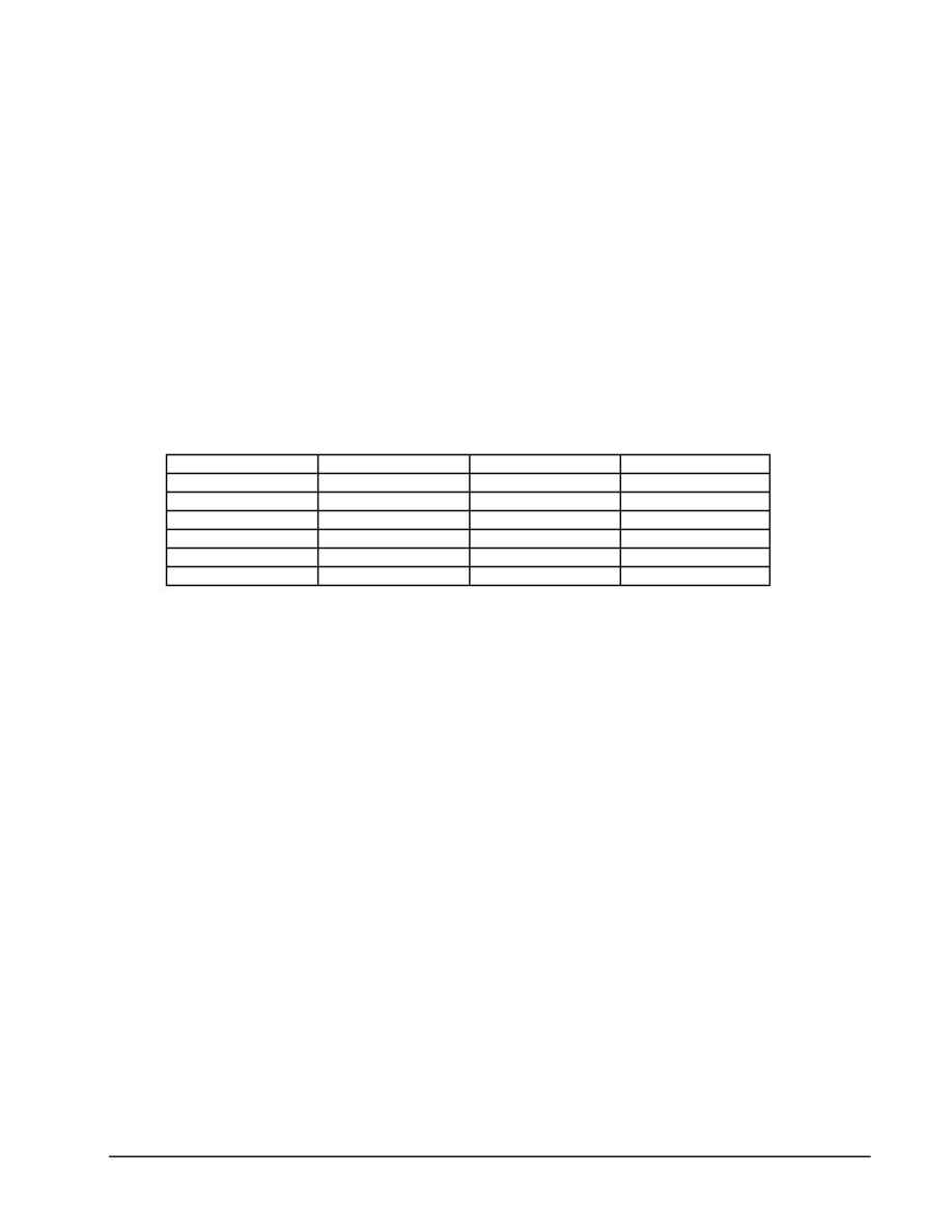
smooth movement in both directions. The following table will help you connect all six combinations:
Table 1. Aid to connect all six motor power lead combinations
Phase A
Phase B
Phase C
Behavior
Power Lead 1
Power Lead 2
Power Lead 3
Power Lead 1
Power Lead 3
Power Lead 2
Power Lead 2
Power Lead 3
Power Lead 1
Power Lead 2
Power Lead 1
Power Lead 3
Power Lead 3
Power Lead 1
Power Lead 2
Power Lead 3
Power Lead 2
Power Lead 1
Once the motor is wired correctly, the controller is ready to perform closed-loop motion.
Brush Motor Setup
To configure an axis for brush motor operation, connect the two motor leads to the Phase A and Phase B connections for
the axis (MX, MY, MZ, MW). Leave the C Phase disconnected. Connect the encoders (15-pin high density X, Y, Z,
W), home switches, and limit switches (AUX I/O J3). The amplifier has no need for the Hall inputs when operating
brush motors.
AMP-19520/40
Setup
·
9
