TECHNICAL REFERENCE
MOTION PROGRAMMING
COORDINATED MOTION
Motion controllers can generate various types of motion.
One of the most common types is coordinated motion
between two axes. In this mode, the controller generates
motion of both motors in a manner that results in
straight lines and circular arcs. This motion is quite com-
mon in computer numeric control (CNC) and other
industrial applications.
Coordinated motion is defined by the path and by the
velocity profile along the path. The first step is to select
the two axes that define the motion plane using the VM
instruction. For example, VMXY defines the plane of
coordinated motion as the XY plane.
The second step defines the motion path which consists
of a collection of straight lines and circular arcs. Straight
lines are defined with the instruction VP m,n where (m,n)
are the coordinates of the endpoint with respect to the start
of the move sequence. Circular arcs are defined with the
instruction CR R,q,d where R indicates the radius, q defines
the starting angle, and d defines the width of the arc.
The complete path may consist of many such motion
segments as illustrated by the following example. There is
no limit to the number of segments that can be specified
and additional segments can be sent during motion. This
allows the DMC to control motion along very long paths
without stopping.
In addition to the motion path, the user can specify
the vector speed (feedrate). In most applications the
feedrate is set to a constant value. However, the velocity
can be reduced around corners. A specific feedrate
may be prescribed for an individual segment. For
example: VP 1000,2000 < 5000 sets the vector speed to
5000 counts/sec for the segment VP 1000,2000.
Similarly, the acceleration and deceleration rates along
the motion can be specified. The instructions for the
vector velocity, acceleration, and deceleration are VS, VA,
and VD respectively.
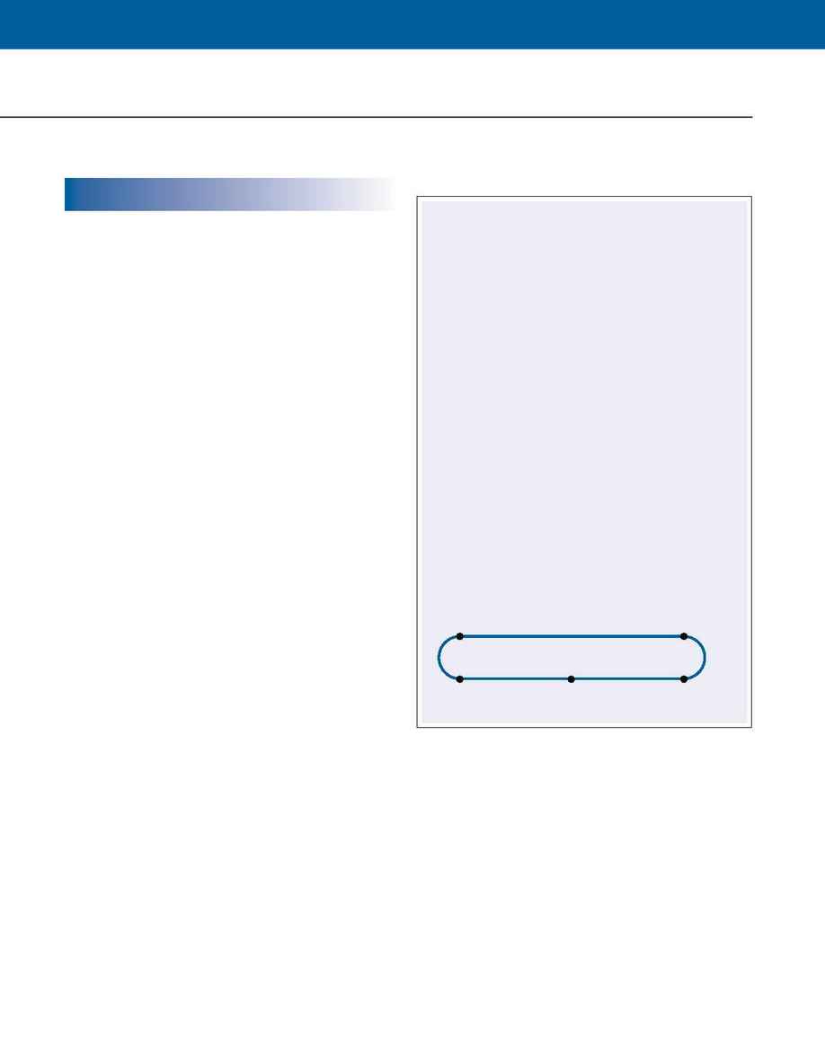
C (6000,2000)
D (-6000,2000)
B (6000,0)
E (-6000,0)
A (0,0)
COORDINATED MOTION
The generation of a coordinated move is illustrated by
the following example. Consider the motion path
described by the figure below and write a program to
generate it. The motion is in the XY plane, the radius of
the corners is 1000 counts, the vector speed is 20,000
count/sec, and the vector acceleration and deceleration
rates are both 100,000 ct/sec2.
The instructions and their interpretations are shown
below.
INSTRUCTION
INTERPRETATION
#M Label
VM XY Specify XY plane
VP 6000,0 Move to Point B
CR 1000,270,180 Move to Point C
VP -6000,2000 Move to Point D
CR 1000,90,180 Move to Point E
VP 0,0 Return to Point A
VE End of path
VS 20000 Vector speed
VA 100000 Vector acceleration
VD 100000 Vector deceleration
BGS Start motion
EN End program
Example--Motion Path for XY
88
·
Galil Motion Control, Inc.
·
www.galilmc.com
