Galil Motion Control note 1419 Page 1

- 1 -
Galil Motion Control, Inc.
·
3750 Atherton Road
·
Rocklin, CA 95765 USA
·
800-377-6329
·
Ph: 916-626-0101
·
Fax: 916-626-0102
·
www.galilmc.com
Application Note #1419
Connecting Loads To Digital Outputs
The uncommitted digital outputs on a DMC-1800 are TTL outputs, provided by a
74ACT273 buffer IC. This IC uses ACT technology. The important difference
between this and other technologies is the maximum currents available. The
74LS273/74ALS273 can sink up to 16mA per output and source 2mA, the
74ACT273 in comparison can both sink and source 24mA per output.
The name TTL (Transistor Transistor Logic) specifies a voltage range, 0 to 0.7 volts
for logic 0 and 2.7 volts to 5 volts for logic 1. These values are a problem, however,
in applications where much larger voltages and currents are needed. For example,
turning on a solenoid or an electric heater can require from 200mA to several amps of
current and may require 110 VAC. A solid-state relay, from OPTO22 or Grayhill for
example, can be connected to the TTL digital outputs to switch these high currents
and voltages. A current of about 12mA typically activates a solid-state relay, so the
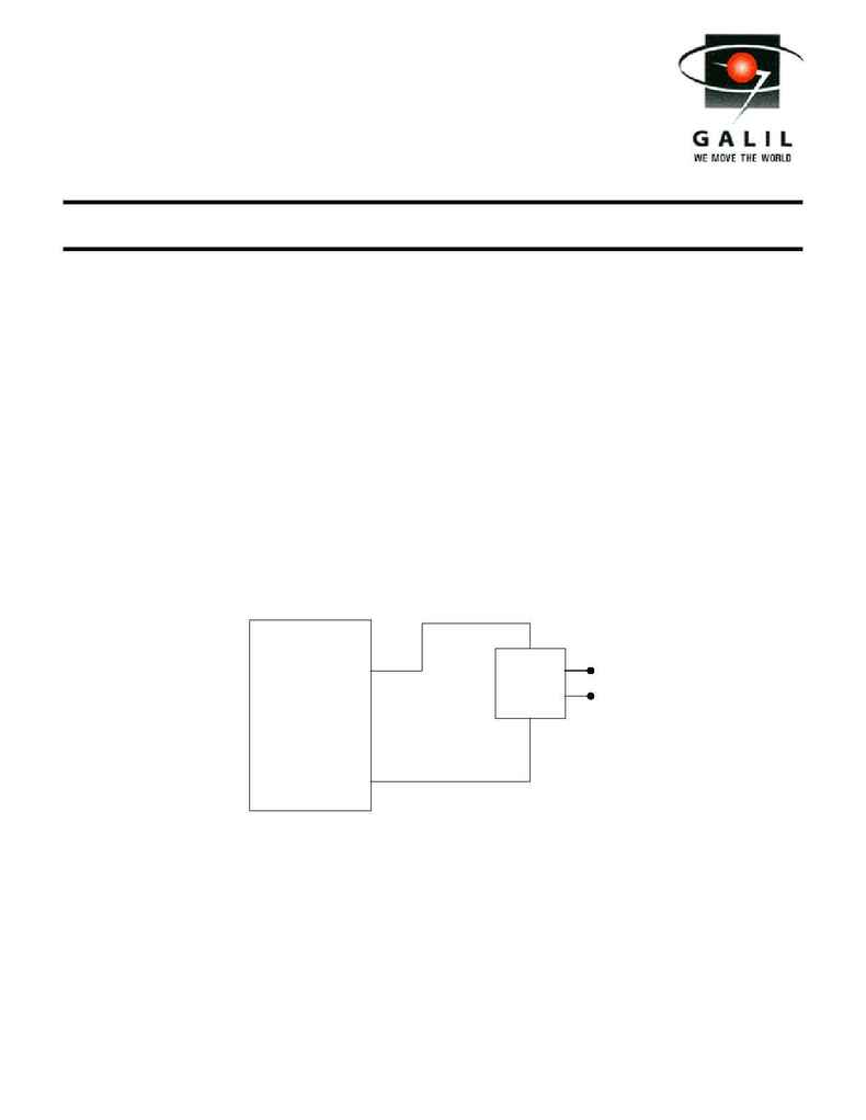
connection is usually done in a sinking configuration. Figure 1 shows how the
connections for a solid-state relay to digital output 1 on a DMC-1800, using the PC
power supply in a sinking circuit:
Solid
State
Relay
DMC-1800 Controller
Output1
5V
to load
Figure 1. Connecting a relay to the DMC-1800 output 1
When using the DMC-1800 controllers with extended I/O (accessed through the DB-
14064 expansion board), the total current required will exceed the current available
through the ribbon cables. An external 5V supply is then used, and the negative of
the power supply is connected to the ground of the controller for reference. When the
digital output is set to logic 0 with a CB command, which is about 0 Volts, then
current flows through the load and the relay activates. This is referred to as negative
true logic.
