Technical References
System Elements
Overview
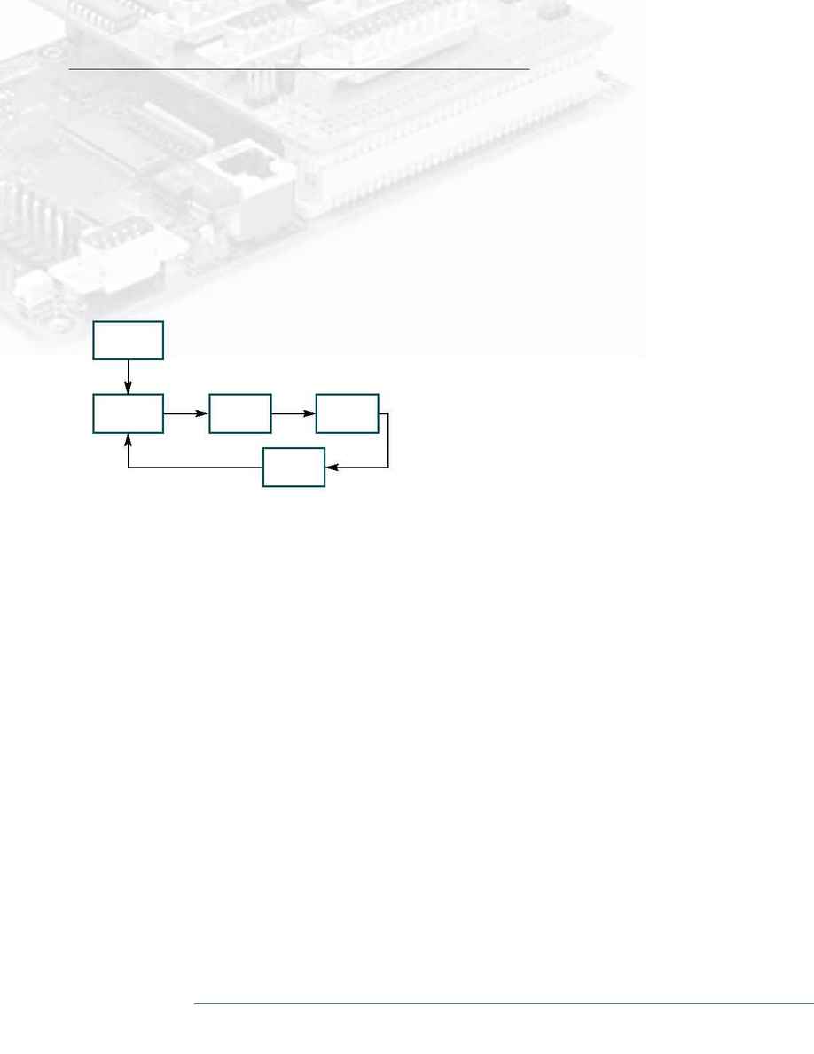
The motion controller is part of a complete closed-loop system
which also includes the power amplifier, motor, and an encoder.
Such systems, also known as servo systems, sense the motor posi-
tion and feed the position signal back to the controller. A typical
servo system is shown in the figure below.
The operation of the various system elements may be
described by comparing the servo system with the human body.
The combination of the motor and power amplifier is analogous
to the muscle that moves the human arm.The motor is the device
that generates the motion; the power amplifier generates the
current required to drive the motor. For example, the amplifier
takes a low-current signal and amplifies it to a higher level of
current of 10 A.
The controller is the intelligent element that commands the
motion. As such, it operates as the brain of the system. It gener-
ates a signal, referred to as the motion command, which is
applied to the power amplifier.The function of the position sen-
sor is analogous to human eyes. It senses the position of the
motor and reports the result to the controller, i.e. closes the loop.
A closed-loop system receives its command from an outside
source, often a host computer. Continuing our human society
analogy, the command source may be seen as the Boss, generat-
ing commands and often requesting status reports.The com-
mands can also be generated by other sources such as a pro-
grammable controller, terminal, or a set of switches.
The following discussion briefly describes the system elements.
The focus is on the most common type of control system, digital
position systems controlling DC motors utilizing incremental
encoders. However, most of the discussion also applies to systems
utilizing AC or hydraulic motors with resolvers or absolute
encoders, etc.
DC Motors
DC motors convert electrical energy to mechanical energy, or more
specifically, convert current into rotational torque.The key parame-
ters of a DC motor are the torque constant K
t
, the armature resist-
ance r, the moment of inertia J
m
, and the maximum torque level.
The torque constant is expressed in units of Nm/A or oz-in/A and
indicates the amount of torque that the motor generates for a unit
of current. For example, a DC motor with a torque constant of 0.1
Nm/A converts a current of 2 A to a torque of 0.2 Nm.The armature
resistance is the total resistance of the armature winding and the
brushes; it is expressed in ohms.The moment of inertia Jm is the
sum of the moments of inertia of the rotating parts of the motor; it
is expressed in units of kg-m
2
or oz-in-s
2
.
A motor is also characterized by the level of torque it can pro-
duce.The motor torque capability is expressed by two parameters:
the continuous value and the peak value.The continuous torque is
what the motor can produce continuously, often at any speed, with-
out overheating.The peak torque is the maximum that can be gener-
ated for short periods of time without causing mechanical damage
or demagnetization.The peak torque is several times the continuous
torque.The motor can generate any level of torque below the peak
torque so long as the root-mean-square (RMS) value of the torque is
within the continuous torque level.
The current that drives the motor is generated by a power ampli-
fier.The operation of such amplifiers is described in the next section.
MOTION
CONTROLLER
POWER
AMPLIFIER
MOTOR
POSITION
SENSOR
POSITION
POSITION
FEEDBACK
POSITION
COMMAND
MOTION
COMMAND
CURRENT
HOST
COMPUTER
Elements of a Servo System
www.galilmc.com
/
Galil Motion Control, Inc.
1
