SWITCH
FUNCTION DESCRIPTION
SETTING
ON
OFF
1
Duty-cycle feedback
On
Off
2
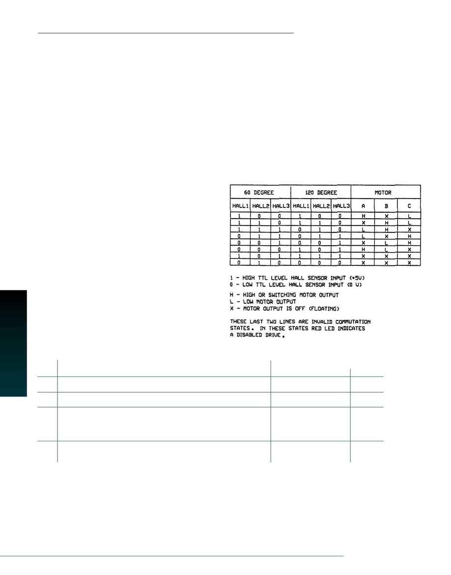
120/60 degree commutation selection
120 degree
60 degree
3
This capacitor normally ensures "error-free"operation in velocity mode by
Shorts out the
Off
reducing the error signal (output of summing amplifier) to zero
velocity/voltage loop
integrator capacitor
4
Offset/test.Sensitivity of the "offset"pot.Used as an on-board reference signal
Increase
Decrease
in test mode.
MBA-6-60
Amplifier for Brushless Motors
Setup
1. Select open-loop mode and switch offset/test switch to "On"
2. Set current limit according to the maximum motor current
3. Check power and connect it to the amplifier
4. Connect HALL sensor inputs.LED should be green.Turn motor shaft
manually one revolution.LED should remain green.If not, change
60/120 degree phasing switch setting (SW2)
5. Connect the three motor wires.There are six ways to connect the
three wires to Motor-A, Motor-B, and Motor-C pins.Try all six combi-
nations and choose the best one. If the motor runs more slowly in
one direction, or if you have to move the shaft to start the motor,
the combination is incorrect
6. Adjust offset/test potentiometer for zero speed, and then switch
offset/test switch to "Off"
7. Set mode suitable for your application
Current Limit Adjustment
Both peak and continuous current limits are adjusted by Pot 2 at the same
time.The peak current limit is twice the continuous limit and lasts for two
seconds.The potentiometer has 15 turns and is linear.Thus, to adjust the
current limit, turn the potentiometer counterclockwise to zero, then turn
clockwise to the appropriate value.P1-15 is the input to the internal cur-
rent amplifier stage.Because the output current is proportional to P1-15,
the adjusted current limit can easily be observed at this pin without con-
necting the motor.The actual current can be monitored at pin P1-8.
Commutation Sequence
Switch Functions
MO
TORS / DRIVES
84
www.galilmc.com / Galil Motion Control, Inc.
