Instruction Interpretation
#RECORD Label
RA YERROR [100] Storage array
RD _TEY Data type
RC 4,100 Actual recording
EN End program
The following example illustrates how recorded data can
be used for analysis.
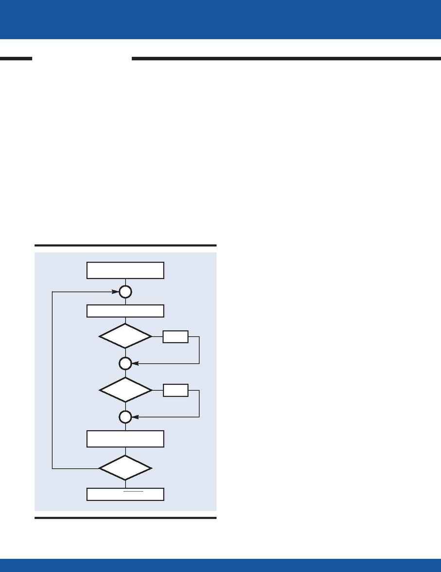
Use the position error data collected in the previous
example to perform a statistical analysis on the position error
of Y. Determine the maximum and the minimum values as
well as the mean square value. The following program per-
forms the required tasks and stores the results under the vari-
ables MAX, MIN, and MEAN.
Instruction
Interpretation
#STAT Label
N = 0 Initial values
MAX = 0
MIN = 0
SUM = 0
#LOOP Label
E = YERROR [N] Read position error
JP#MAX, E<MAX Compare with MAX
MAX = E Redefine MAX
#MAX Label
JP#MIN, E >MIN Compare with MIN
MIN = E Redefine MIN
#MIN Label
SUM = E*E+SUM Compute sum of squares
N = N+1 Increment index
JP#LOOP, N<100 Repeat 100 times
MEAN = SUM/100 Mean square
ROOT = @ SQR[MEAN]
Root mean square (RMS)
EN End program
Coordinated Motion
Motion controllers can generate various types of motion.
One of the most common types is the coordinated motion
between two axes, for example, X and Y. In this instance, the
controller generates motion of both motors in a manner that
results in straight lines and circular arcs. This motion is quite
common in computer numeric control (CNC) and other
industrial applications.
Coordinated motion is defined by the path and by the
velocity profile along the path. The first step is to select
the two axes that define the motion plane using the VM
instruction. For example, VMXY defines the plane of
coordinated motion as the XY plane.
M O T I O N C O N T R O L P R O G R A M M I N G
108
Motion Control Programming
·
Galil Motion Control, Inc.
·
800-377-6329
N<100
E<MAX
E>MIN
N=0 MAX=0
MIN=0 SUM=0
SUM=E*E+SUM
N=N+1
RMS=
SUM /100
READ DATA POINT E
MAX=E
NO
MIN=E
NO
NO
YES
YES
YES
Flowchart for #STAT
COORDINATED
MOTION
