M O T I O N C O N T R O L P R O G R A M M I N G
104
Motion Control Programming
·
Galil Motion Control, Inc.
·
800-377-6329
which reads the digital input #2 and stores its content, 0 or
1, in the variable DIGITAL. Analog signals are similarly read
with the instruction:
ANALOG = @ AN[3]
which reads analog input #3.
Digital output signals are generated by setting or clearing
a bit with the instructions:
SB 3
CB 3
which sets and clears output bit #3.
The interface with the inputs and the generation of the
output signals allow the controller to perform complete
process control without a host computer intervention. This is
illustrated by the following example.
Consider the simple case where the motion of X must be
delayed until the start pulse is given (applied to input 1).
When the motion is completed, an output signal (output 1)
must be given for one second.
Instruction
Interpretation
PR 7000 Distance
SP 5000
Speed
AI 1 Wait for start signal
BGX Start motion
AMX Wait for completion
SB 1 Set output 1 high
WT 1000 Wait 1 second
CB 1 Clear output 1
EN
End of program
Trippoints
Another function of advanced motion controllers is to
schedule or sequence events in a program. These functions
are scheduled by delaying the execution of each function
until a certain condition occurs. These conditions are
called trippoints.
For example, the "After Distance" (AD) trippoint delays
the execution of a function until after the motor moves a
certain distance. Similarly, the execution of a function can be
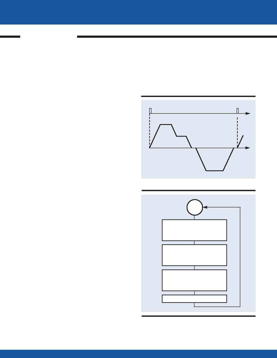
TRIPPOINTS
AFTER A DISTANCE
OF 6000 COUNTS
SPEED=10000
WHEN MOTION IS COMPLETE WAIT 100 ms
MOVE BACK 10000
AT SPEED 20000
DISTANCE=10000
SPEED=20000
WAIT FOR INPUT 1
START THE MOTION
CYCLE
WHEN MOTION IS COMPLETE
INPUT 1
TIME
TIME
-20000
20000
10000
VELOCITY
Flowchart for #Cycle
Motion Cycle using Trippoints
