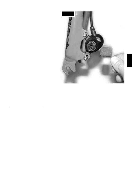
3. When installing the pads, it may be nec-
essary to back the caliper adjusters out by
turning them counter-clockwise with a
5mm hex wrench. This will allow enough
clearance in the caliper slot to be able to
slide each pad into its respective side of
the caliper. The 5mm Allen screw on the
bleed screw side of brake adjusts the posi-
tion of the piston activated pad, while the
5mm hex screw on the other side of the
brake adjusts the position of the fixed pad.
Note that the fixed (right) side pad adjuster
does not have a stop and can be com-
pletely unscrewed from the caliper. If this
happens, put a drop of Loctite 242 (blue)
on the threads and reinstall the pad
adjuster into the caliper.
4. Install the pads one at a time by simply
holding the tab on each pad and sliding
each pad into the rotor slot and then into
the square hole on each side of the slot
(see Fig. 3.) The pin on each piston must
mate with the hole in the back of each
pad, and the tabs of each pad will stick out
of the caliper near the lower caliper
mounting bolt. Again, make sure that the
correct pad is installed in each side of the
caliper.
5. Pads can be removed by simply grasping the steel tab on each, lifting the pad out of the square
hole in the caliper, and maneuvering the pad out through the rotor slot in the body of the caliper.
MOUNTING BRAKE LEVERS
Note: The CODA Expert Disc Brake system comes assembled with the left brake lever attached to
the front caliper and the right brake lever to the rear caliper. If you would like to reverse this arrange-
ment, simply flip the lever over and install it on the other side of the handlebar. The brake levers are
symmetrical and can be used on either side of the bar. The lever clamp bolt and nut may also be
removed and reversed so that the bolt is accessible from either side of the lever.
1. Slide the brake levers onto the handlebar with brake lines pointing toward the center of the handle-
bar, as you would any standard mountain bike type brake lever. Generally, push button type shifters
will need to be installed on the bar before the brake levers, while twist shifters will go on after the
brake levers.
2. Tighten the shifters and install the grips per the manufacturers' instructions.
3. Once the brake levers and shifters have been positioned as desired, tighten the brake lever bolts to
72-108 In-Lbs (8-12 Nm.)
4. The reach of each brake lever can be adjusted closer by turning the 2mm hex head lever adjusting
screw clockwise. This will also move the pads closer to the brake rotor. If you adjust the reach of the
brake levers after having set up the brakes, it may be necessary to readjust the pad clearance with
the two 5mm hex screws on the caliper. See the "PAD ADJUSTMENT" section below.
WARNING: Do not remove the 2mm brake lever adjusting screw from the lever body. It holds the
lever pivot in place. Removal of the brake lever adjusting screw could result in the brake lever falling
out of the master cylinder, with attendant loss of braking and risk of injury or death.
5.
Fig. 3
