use the position on the large radius.
5. Note that there are five (5) spring ear holes in the lockout cam. Install the spring into the
cam hole nearest the cable set screw, then install the cam onto the lockout shaft (see Fig.
7). Now preload the spring by turning the cam approximately 180 degrees clockwise. The
lockout shaft should remain in place while doing this. When the cam set screw lines up with
the flat portion on the lockout shaft, tighten the set screw (see Fig. 8). CAUTION: Over-
tightening this screw may strip its threads. Very little torque is required, less than
can be accurately measured by a torque wrench (3 In-lbs/0.3 Nm). Hold the short end
of the hex wrench and insert the long end into the screw when you tighten.
Cable and Housing
1. Route the 1.1mm derailleur cable through the lockout lever towards the rider and run it
through the cable stop closer to the rear of the bike. Before installing the 4mm derailleur
housing, make sure that both ends are round and are cut flat. Run the cable through the
housing, set the housing (without a ferrule) firmly into the lever's cable stop, and set the
lever to the locked out "down" position (see Fig. 9). Run the cable and housing back to
the shock along your pre-determined route. Remember to choose the least restrictive
routing possible that does not interfere with steering, water bottle access, drivetrain ope-
ration, or rear shock/swingarm action. Put a ferrule on the end of the housing at the cable
stop bracket and insert it into the bracket; leave the end of the cable loose.
cable stop bracket mounts to the shock accordingly. On Cannondale Scalpels, the cable
should run along the top tube and approach the shock from above, using the Rollamajig.
Jekylls and Geminis should be set up with the cable and housing running along the down
tube and looping up to approach the shock from behind (see Fig. 4). If you're mounting
Remote Rear Lockout on any other bike equipped with a compatible Fox shock, choose
the least restrictive routing possible that does not interfere with steering, drivetrain
operation, rear shock/swingarm action, or waterbottle access.
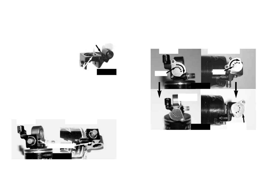
3. Apply a light coat of grease to the torsion spring and
seat it in the cable stop bracket with the spring ear
facing up (see Fig. 5). Place the bracket and spring
over the lockout shaft on the shock so that the cable
stop points in the direction of your cable and housing
(see Fig. 6). Secure the bracket and spring by repla-
cing the lockout shaft set screw with the included dog-
point low-head 2mm socket cap screw.
CAUTION: Overtightening this screw may strip its
threads. Very little torque is required, less than can
be accurately measured by a torque wrench (10 In-lbs/1.1 Nm). Hold the short end
of the hex wrench and insert the long end into the bolt when you tighten.
NOTE: When tightened, the tip of the dogpoint screw sits in a groove on the lockout
shaft. It does not actually contact the shaft. If the dogpoint screw is installed properly, you
should be able to rotate or lift the lockout shaft a little with your fingertips. If the shaft
does not move at all, loosen the dogpoint screw and make sure that it's sitting freely in
the shaft's groove before re-tightening.
CAUTION: If the dogpoint screw contacts some part of the shaft and stops it from
rotating, the shock will be stuck in the locked position. If forced to unlock, the
shaft, screw, and the shock itself may be damaged, potentially beyond repair.
4. Now choose a lockout cam set screw position. If your cable stop bracket faces away
from the shock body (Scalpel), thread the cam set screw into the position on the small
radius of the cam. If the cable stop faces towards the shock body (Jekyll and Gemini),
4
5
Fig. 55
!
SCALPEL
JEKYLL OR GEMINI
Fig. 66
!
Dogpoint screw
Spring
SCALPEL
JEKYLL OR GEMINI
Tighten cam
set screw
Tighten cam
set screw
Spring
Spring
Fig. 77
!
Fig. 88
!
Cable Stop Bracket
