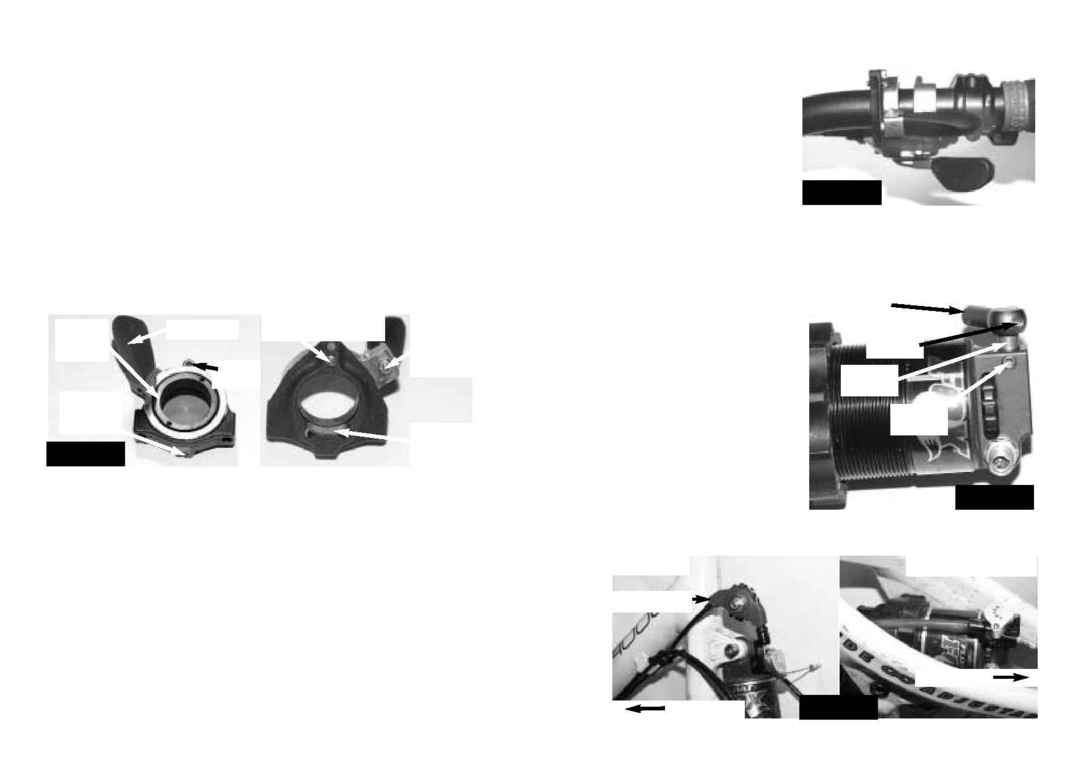
the shifter (leave more room if you ride
with gloves). See Fig. 2
3. Finally, check to make sure that the
lockout lever's bearings are adjusted
properly. Completely back off the detent
preload screw (approx. 2.5 to 3 turns -
don't remove it completely) and move
the lever several times along its full ro-
tation (approx. 60 degrees). If the bear-
ings roll smoothly, reset the detent pre-
load and continue with the installation. If
the bearings are too tight (you feel grittiness or resistance) or too loose (you feel lateral
play), loosen the lockout lever set screw and use circlip pliers to loosen or tighten the inner
bearing race (see Fig. 1). When the bearings are adjusted properly, reset the detent
preload, tighten the lockout lever set screw, and continue with the installation.
FOX Shock Setup
1. Lock out the rear FOX shock. Note
that all following instructions require that
the shock be locked out it's important,
so double-check. Bounce on your bike
with the blue FOX lever in various posi-
tions to make sure that the shock is
locked out. With the FOX lockout lever in
the locked-out position, loosen the lever
set screw and remove the lever from the
lockout shaft (see Fig. 3). Now remove
the shaft set screw, leaving the shaft in-
stalled in the shock.
2. Decide how to run cable and hou-
sing from the handlebar to the shock.
The cable and housing can approach the shock from either end, along its long axis. The
Make sure all of the above parts are present, including two set screws that should be in-
stalled in the cam. Apply a drop of Loctite 242 (blue) to the low-head 2mm dogpoint
socket cap screw and the two cam set screws. NOTE: These instructions are written to
get you through a complete install and setup of the Remote Rear Lockout. If the lockout
lever and the cam assembly are already installed on your bike, skip to the section called
"Cable and Housing" on page 6.
Lockout Lever Setup
1. The lockout lever comes set up for use on the right side of the handlebar. If that's
where you want it, skip to step 2. To use it on the left side of the handlebar, remove the
thumblever screw and the stop screw, rotate the lever past the detent pin (decreasing
detent preload by a couple of turns will make this easier, see Fig. 1), and reinstall the
thumblever and stop screws.
CAUTION: Overtightening these screws may strip their threads. Very little torque
is required, less than can be accurately measured by a torque wrench (4 In-
lbs/0.5 Nm). Hold the short end of the hex wrench and insert the long end into
the bolt when you tighten.
2. The lockout lever should be positioned inboard of both the shift and brake levers, with
the thumblever facing away from the stem and overlapping the shift lever clamp. To in-
stall it, remove everything from the side of the handlebar where you're placing the lockout
lever. Ensure that the handlebar clamp plate is in position and has not fallen out. Slide
the lockout lever onto the handlebar and leave it loose on the bar. Reinstall the items you
just removed from the handlebar and tighten them back into place. Rotate the lockout
lever so that its cable stops are pointing down, slide it all the way until it touches the shif-
ter, back it away just a hair, and tighten the lockout lever set screw just enough so that
you aren't able to rotate the lever on the bar. WARNING: Overtightening the lockout
lever onto the handlebar may damage the bar, potentially causing the handlebar to
fail and resulting in injury or death to the rider. Do not overtighten the lever.
It's very important that the lever doesn't interfere with the movement of the Rapidfire shif-
ter paddles. Before proceeding, make sure that the lockout lever and shifter paddles do
not make contact at any point of their travel, and that there's enough room to fit your
thumb between the thumblever in its locked-out ("down") position and the big paddle on
2
3
Fig. 11
!
Lockout
Lever Set
Screw
Inner
Bearing
Race
Stop
Screw
Handlebar
Clamp
Plate
Thumb-
lever
Screw
Detent Preload Screw
Thumblever
Fig. 22
!
FOX Lockout
Lever (blue)
Lever Set
Screw
Lockout
Shaft
Shaft Set
Screw
Fig. 33
!
JEKYLL OR GEMINI
Front of Bike
Front of Bike
Fig. 44
!
Rollamajig
SCALPEL
