1
3
2
5
6
a
4
7
8
10
b
9
11
power sensor
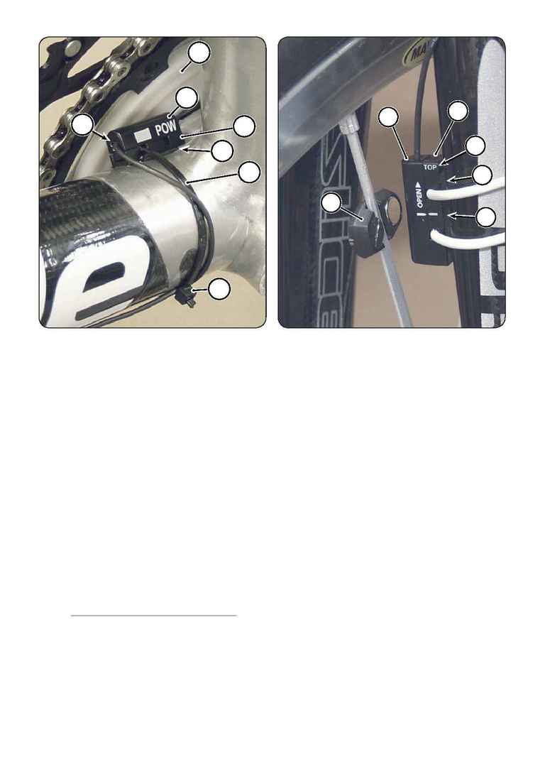
· The power sensor (1) is marked `POW
·
Sensor gap = 2 - 4mm
If the POW sensor is mounted too far from white
cover (2) or with the wire (3) exiting the `POW` sensor
towards the rear wheel the Powermeter computer
will not switch on.
· Position the sensor close to the downtube seat tube
intersection with the wire pointing toward the head
tube as shown. Do not install with the wire pointing
toward the rear wheel. Make sure the foam footing
(4) is in place under the sensor base (5). Secure the
base with a 3.5 mm zip tie (6). Route the wire under
the zip tie head (a) as shown.
Troubleshooting
There should not be any interference between the white
plastic spider cover and the frame.
Interference can be caused by incorrect crankarm
installation. You can use 3 - 5 black spacer spacers. See
the SI Crankset owner's manual supplement in our Tech
Center:
http://www.cannondale.com/bikes/tech/
.
speed sensor
· The speed sensor (7) has "SPEED" printed on the wire
and should be mounted to the fork leg with the "TOP"
(8) marking up. Make sure the foam (9) is under the
base (10).
Place the magnet (3) on the spokes so it passes across the
white line (b) on the middle of the mounted sensor.
·
Sensor gap = 3 mm
· A rear wheel mounted speed sensor is available through
SRM directly.
