E.5
CHAPTER ONE
Guide to Safe Child Carrier Use
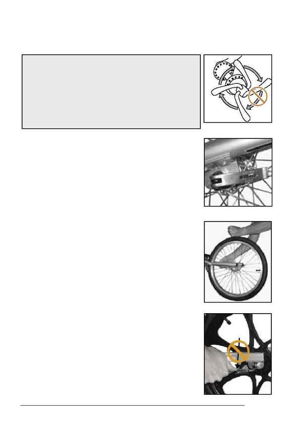
6. Orient the quick-release levers so they do not
interfere with any other child carrier part or
accessory part, and so obstacles in the path of
the child carrier cannot snag the lever (Figure
1.12).
7. Test that you have properly adjusted and
closed the quick-release. If the quick-release
fails any test, either repeat these adjustment
procedures, including these tests, or take the
child carrier to your Trek dealer for service.
Test for proper lever-type quick-release adjust-
ment
· Pick up the child carrier, and sharply hit the top
of the tire (Figure 1.13). The wheel must not
come off, be loose, or move from side to side.
· Make sure the quick-release lever cannot be
rotated parallel to the wheel (Figure 1.14).
· When the quick-release is properly tightened,
and clamped by the lever in the closed position,
the clamping force is adequate to cause metal-
into-metal engagement (embossing) of the
dropout surfaces.
· See Figure 1.11.
Figure 1.10- Do not turn the
lever
Figure 1.12- Front lever position
Figure 1.14- Test for rotation
Figure 1.13- Test for looseness
If it requires more than 45 pounds (200
Newton) force to completely close the quick-
release lever, open the lever and slightly loosen
the quick-release adjusting nut.
If it requires less than 12 pounds (53.4
Newton) force to begin to open the lever from
the fully closed position, open the lever and
slightly tighten the quick-release adjusting nut.
Repeat the adjustment if necessary.
Figure 1.11 Definition of correct quick-release lever force
