Rotor
A rotor (Fig. 61) allows the handlebars on a freestyle bike to rotate 360
degrees despite having a cable operated front brake. Since the rotor is a
connection between the brake lever and the brake, its function is critical
to good stopping power and safety.
Once a month inspect the rotor for proper function. Watch the bearing
unit as you rotate the handlebars 360 degrees. It should not move up or
down, or tilt. When the brake lever is applied, the rotor should apply the
brake firmly while the bearing unit remains parallel to the upper and lower
cable stops. If the bearing unit tilts either when the brakes are applied, or
when the handlebars are rotated, the rotor needs adjustment.
To adjust the rotor, first ensure that both lower barrel adjusters are flush
with (do not show above) the lower cable stop, and the bearing unit should
be resting on the lower cable stop. Your rear brake adjustment must be
made with the bearing unit in this position.
The bearing unit should be parallel to the upper and lower cable stops. If
it is tilted, there is slack in one of the cables. Pull each end, one at a time.
to see which cable has slack at the bearing unit. Remove the slack through
the barrel adjuster. When even pull is achieved tighten all barrel adjuster
locknuts.
If you are unsure of the brake adjustment, or suspect any problem, do
not ride your bicycle. Take your bicycle to your dealer for service. It is
strongly recommended that adjustment of critical components such as
brakes be done by your dealer.
Caliper brakes
Caliper brakes (Fig. 60) are a rim brake. Rim brake information is
covered on pages 20-21.
Cable Installation
To install a brake cable in Shimano Inter M brakes, note the path of the old cable,
loosen the brake cable anchor bolt and remove the worn cable. Turn the adjusting
barrel on the brake or lever fully clockwise. Grease the new cable and reinstall, feeding
it along the same path as the old cable. Make sure that the cable's leaded end is seated
properly in the brake lever body and that the housing is properly seated in the lever.
After threading the cable through the anchor bolt, follow the directions for brake
adjustment in the Adjustment section.
After the brakes are adjusted, test the brakes by applying maximum braking force to the
levers. Ensure that the cable does not slip in the cable anchor bolt.
Finally, cut the cable so that no more than 2 inches (51 mm) extends beyond the anchor
bolt. Crimp a metal cap or place a bit of solder on the end of the cable to prevent fraying.
23
22
ROTOR AND CALIPER BRAKES
DISC BRAKES
Fig. 60
Fig. 61
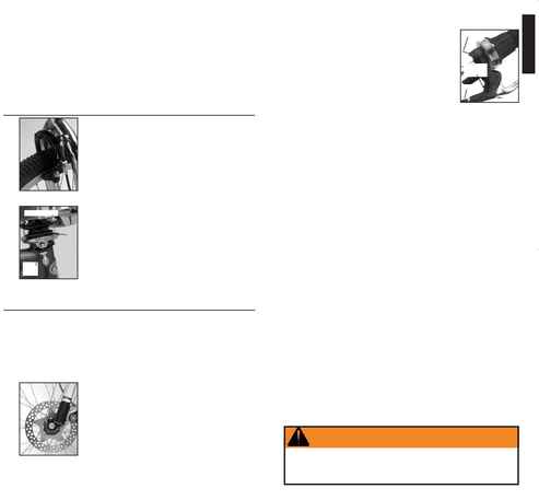
Inspection
Before every ride make sure your brakes are working properly. Check that the brake pads are
in proper position. The pads should allow 0.25 to 0.75mm clearance from the disc when the
brakes are not applied. Spin the wheel. When the brake lever is not pressed, the brake pads
should touch as little as possible on the rotor (Fig. 62). Do not touch disc brake rotors after
hard use as they may be very hot. For cable actuated brakes, tighten the cable clamp bolt to
50-70 lb·in (5.7-7.9 Nm)
Before every ride squeeze the lever firmly. It should not be possible to pull the lever fully to
the handlebar. If the lever of a hydraulic activated disc brake feels spongy, or can be pressed
with little resistance, the system may need to be bled to remove air
bubbles. Take your bike to your dealer for service. If the lever of a cable
actuated disc brake can be pulled to the handlebar, follow the adjustment
instructions in the following section.
Once a month tighten the disc brake mounting bolts, and any adapter
mounting bolts, to 60 lb·in (6.8 Nm). Tighten rotor attachment bolts
holding the rotor to the hub to 45-55 lb·in (5-6.2 Nm). Tighten Hayes
hydraulic brake lever attachment bolts to 25-35 lb·in (2.8-4 Nm).
The rotor is part of the braking system, so keep it clean at all times.
Check that there is no oil, grease, or other dirt on the rotor. Remove the
brake pads from the caliper during heavy cleaning by pulling outward to
release the spring clip. Do not use cleanser, degreaser, or solvents to clean
the disc. To clean discs, use isopropyl alcohol.
With hydraulic actuated disc brakes, check the brake hose for kinks or
leakage every month. Replace any part of hydraulic hose which does not
pass inspection. Replacing hydraulic hose requires re-adjustment of the
braking system with special tools and training and should only be done by
your dealer. Do not let brake hydraulic fluid contact the bicycle as it may remove paint.
With cable actuated disc brakes check your bike's brake cables and housing every month.
Fig. 62
Check the cables for kinks, rust, broken strands, and frayed ends. Check
the housing for bent ends, cuts, stretched coils, and wear. Replace any part
of your brake cables or housing which do not pass inspection.
Every month, inspect disc brake pads for wear. If disc brake pads are less
than 1.0 mm thick they should be replaced.
Adjustment
On some models of bicycles, the distance from the handlebar grip to the
brake lever can be adjusted to fit your hand size. To adjust the reach,
squeeze the brake lever while turning the reach adjustment screw (Fig. 63).
On brake levers for hydraulic activated disc brakes, the reach adjustment
screw may be at position `B'. Try the different settings until you find a
position that fits your hands. After adjusting the brake reach, you may
need to re-adjust the brake cable length by rotating the barrel adjusters, as explained in the
following paragraphs.
Disc brakes are essentially self adjusting as long as the brake is correctly aligned and
centered over the disc rotor. If the rotor is rubbing, the brake caliper alignment may need
adjustment. To make this adjustment, first loosen the brake attachment bolts. While applying
the lever fully, gradually tighten each attachment bolt as specified in Inspection.
Do not operate the disc brake lever when the rotor is not in the caliper. Self adjusting disc
brakes automatically set the distance from the pad to a point of contact, usually the rotor.
However, if the lever is pulled with the rotor removed from the brake, the pad clearance will be
set from the opposing pad. This results in only 0.5mm between the pads so the rotor can not be
re-inserted in the brake. To fully open the pads, remove both brake pads by pulling outward on
the small pad tab. With a 12mm box end wrench, push each piston out as far as it will go being
careful not to press on the brake pad locating post. Reinstall the pads by sliding them into
position, reinstall the wheel, and check the brake adjustment as in Inspection.
If the brake lever of a cable actuated disc brake can be pulled fully to the handlebars, adjust
the brake cable tension. To do this turn the brake cable adjusting barrels found on the brake
levers. To decrease the lever travel necessary to actuate the brake, turn the adjusting barrel
counter-clockwise. To increase lever travel, turn the adjusting barrel clockwise. If the lever
travel cannot be adequately adjusted in this manner, loosen the cable anchor bolt on the brake
until the cable is loose. Screw the barrel adjuster all the way in clockwise. Pull the cable taught
and follow the procedures in Inspection to re-tighten the cable anchor bolt. After the brakes are
adjusted, test the brakes by applying maximum braking force to the levers. Ensure that the
cable does not slip.
Lubrication
Every 3 months, lubricate your brake lever pivots with Wrench Force® synthetic chain lube or
a similar light oil. Disc brakes require no lubrication.
Lubricate brake cables with a thin layer of Wrench Force® synthetic grease or a similar
lubricant when installed.
Cable Installation
To install a brake cable in cable actuated disc brakes, note the path of the old cable, loosen
the brake cable anchor bolt and remove the worn cable. Turn the adjusting barrel on the brake
lever fully clockwise. Grease the new cable and reinstall, feeding it along the same path as the
old cable. Make sure that the cable's leaded end is seated properly in the brake lever body and
that the housing is properly seated in the lever. After threading the cable through the anchor
bolt, follow the directions in the Inspection and Adjustment sections. Finally, cut the cable so
that no more than 2 inches (51 mm) extends beyond the anchor bolt. Crimp a metal cap or place
a bit of solder on the end of the cable to prevent fraying.
Fig. 63
WARNING
Disc brakes can get very hot and could cause burns. Do not touch the
rotor (brake disc) for at least 30 minutes after braking.
Keep away from parts like rotors and spokes when rotating. They may
cause personal injury.
Upper cable stop
Lower
cable
stop
Bearing
unit
Lever clamp bolt
Reach
adjustment
screw
Cable
Barrel
adjuster
B
ENGLISH