where f
a
and f
b
are the focal lengths along the long (2a) and short (2b) dimensions. A CTE of
and a temperature gradient
= 5 mK/m produce focal lengths of 2.5 and 5.0
a
=
2 $ 10
-
8
K
-
1
gigameters. At the edge of the beam launched toward the primary (
=30 cm), the wavefront
from such a mirror would lag the wavefront center by about 18
pm. This represents an insignifi-
cant wavefront error. However, static thermal gradients are on the order 5
K/m. Such gradients
along the CMA would produce a wavefront error of order ~18 nm, or ~
/30 at
= 550 nm. The
optical design goal is to achieve a wavefront error of 4 nm
. It appears that the likely thermal gra
-
dients will cause a wavefront error many times this large.
3. Transverse Gradient Case.
3.1. Derivation of the Surface Perturbation.
Recall eq. (1):
(18)
u
=
a b
1
2
z
2
-
q
2
z q
0
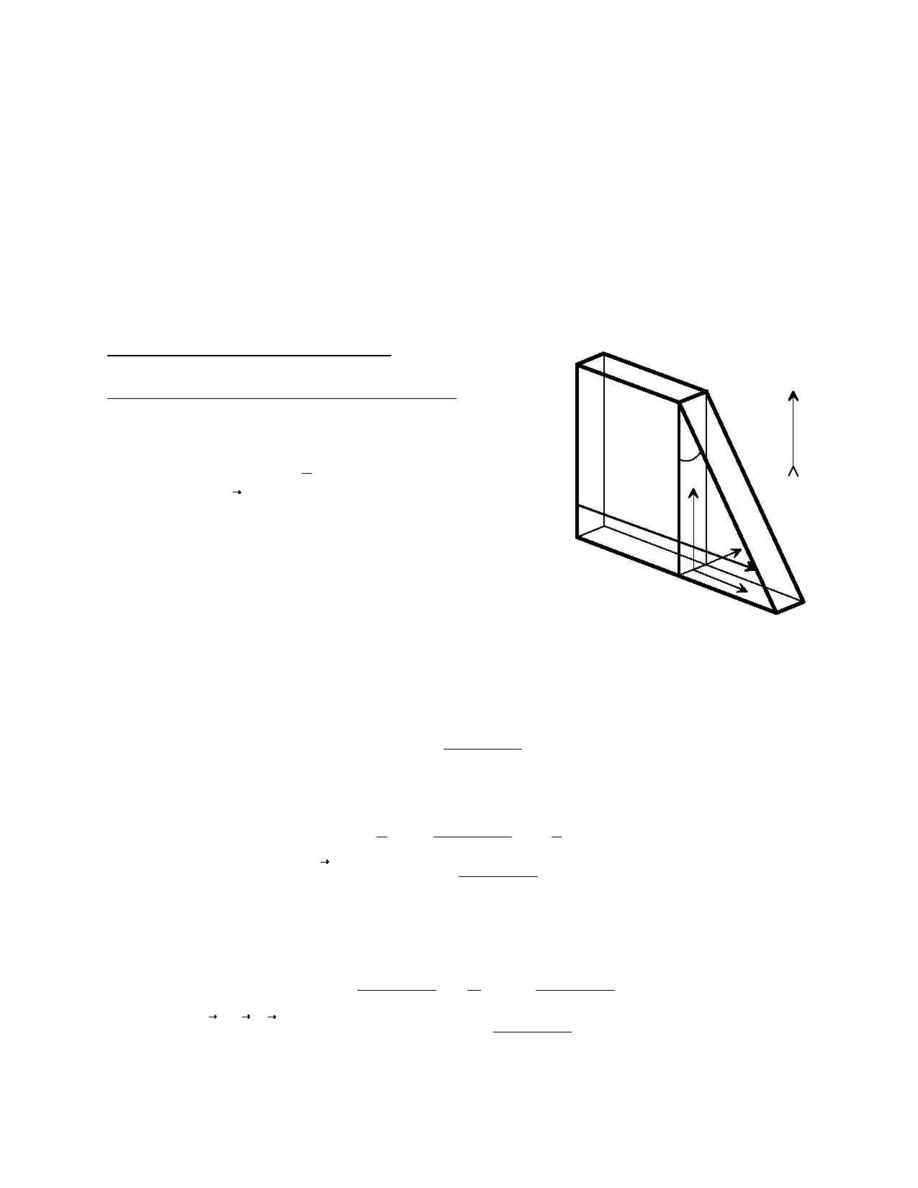
For the transverse case, we rotate the coordinates
so that
the z axis is again parallel to the temperature gradient
(Figure 6). Eq. (18) then applies without change. The
unperturbed surface is now expressed in the form
(19)
s
=
h
+
(2 a
-
z) tan x
=
q cos h
so that the mirror plane is described by the constraint equation
(20)
z
=
2 a
+
h
-
q cos h
tan x
Hence the perturbation at the surface is
(21)
u
=
c
1
2
2a
+
h
-
q cos h
tan x
2
-
1
2
q
2
2 a q
+
h
-
q cos h
tan x
q
0
so that the perturbed surface has the form
(22)
r
┬
=
r
+
u
=
2a
+
h
-
q cos h
tan x
+
1
2
2a
+
h
-
q cos h
tan x
2
-
q
2
c
q
1
+
2a
+
h
-
q cos h
tan x
c
h
Basic Angle Temperature Gradient Sensitivity
FTM-USNO-95-01
8
2a
2b
s
x
y
z
h
Figure 6
