REFERENCES:
MACHINERY'S HANDBOOK EIGHTEENTH EDITION
NOTE:
Always begin a new case by retrieving the original file. Direct entry of data in cells that
originally contain table lookups could cause functions to be lost, or incorrect calculations.
I format cells requiring entry colored
RED
; calculated values are black.
BASIS:
The usual method of calculating the moment of inertia of a built-up section involves the calculations
of the moment of inertia for each element of the section about its own neutral axis, and the
transferring of this moment of inertia to the previously found neutral axis of the whole built-up section.
A much simpler method that can be used in the case of any section which can be divided into
rectangular elements bounded by lines parallel and perpendicular to the neutral axis is the so-called
tabular method. (continued below)
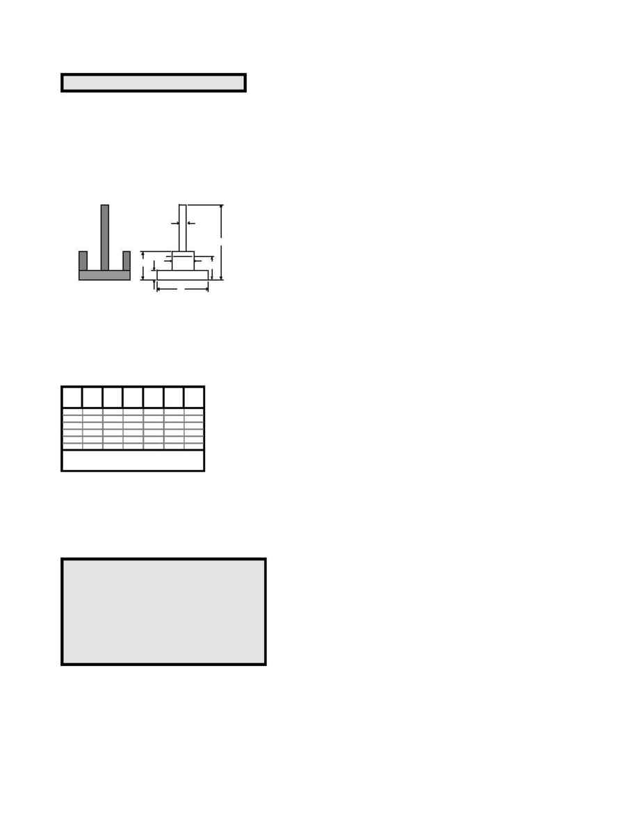
Fig. 1
Fig. 2
This method is illustrated by applying it to the section shown in Fiq.1 and for simplicity of calculation
shown "massed" in Fig.2. The calculation may then be tabulated as shown in the following table. The
distance from the base to the neutral axis x-x is found by dividing the sum of the geometrical moments
by the area. The moment of inertia about the neutral axis is then found in the usual way by subtracting
the area multiplied by d
2
from the moment of inertia about the base.
Breadth
Height
Disp
Area
M
IDE
Section
b
h
1
y
b*( h
1
- y )
b*(h
1
2
-y
2
) / 2 b*(h
1
3
-y
3
) / 3
(from base)
Plate A
1.5
0.125
0.0000
0.1875
0.012
0.001
Plate B
0.531
0.625
0.1250
0.2655
0.100
0.043
Plate C
0.219
1.5
0.6250
0.1916
0.204
0.229
Plate D
0
0
0.0000
0.0000
0.000
0.000
Plate E
0
0
0.0000
0.0000
0.000
0.000
Plate F
0
0
0.0000
0.0000
0.000
0.000
Max. combined ht.
3.5
0.6446
0.315
0.272
·
distance from base to the neutral axis ......
d = M/A =
0.49
inches
·
moment of the entire section.....
I = IDE - A
*
d
2
= 0.119
in
4
Print out using direct EXCEL commands.
dmcoffman@aol.com
Consistent with GOOD ENGINEERING PRACTICE, t h e burden rests with t h e USER of these
spreadsheetst o review ALL calculations, and assumptions. The USER IS FULLY RESPONSIBLE for t h e
results or decisions based on calculations.
This Spreadsheet Requires MACROS t o b e ENABLED t o ASSURE proper operation. See t h e Workbook
Help Sheet for Additional Instructions on Use.
PROPERTIES of BUILT-UP BEAM & ANGLE SECTIONS
<<<<<<<< Psafety © January 2001, by Don Coffman >>>>>>>>
Theoriginator of these spreadsheet(s) specifically excludes all warranties, expressed or implied,as t o t h e
accuracy of t h e dataand other information set forth and assumes NO liabilityfor anylosses or damage
resulting from the use of the materials or application of the data.
1.5"
0.219"
0.125"
x
x
0.531"
0.49"
0.625"
1.5"
A
B
C
section
Psafety© January 2001
