THE MODEL ENGlNEER
is a double-ended arbor which is, a press fit in the
boss of the front motion-plate, so that the lever
straddles the plate when in position. Note that
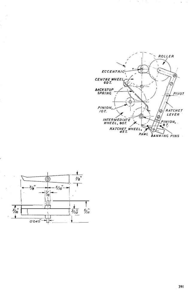
the feed paw1 must be made tail-heavy, so that
it is kept in engagement with the ratchet wheel
by gravity. (Fig. 18.)
The backward movement of the ratchet lever,
and the depth of " bite " of the pawl, are limited
by banking pins fitted to the front motion plate ;
in the former case, the pin prevents the roller
following the eccentric right to the bottom of its
stroke, so that under conditions of variable
balance action, the length of stroke of the paw1 is
fairly constant, or at any rate, never sufficient to
enable it to gather `more than one tooth of the
ratchet wheel. But if, for any reason, excessive
banking pins beforehand, they are-located as close
as possible to their presumed positions and
adjusted by bending.
The ratchet wheel is prevented from moving
backwards, on the return swing of the ratchet
lever, by a simple backstop spring, which, as
already mentioned, is anchored by a screw to a
lug cast on the motion plate, below the pivot
bearing housing. This spring should be very
light, or it will be noisy in action and also cause
unnecessary friction in operating the ratchet
wheel. A piece of pendulum suspension spring,
bent at the end to the shape shown in Fig. 19,
may be used for this purpose, and the hole for
the anchoring screw may, with advantage, be
elongated so that the spring can be adjusted to a
nicety, to drop lightly into engagement with the
teeth of the wheel as the ratchet lever comes to
the end of its stroke.
MARCH 31, 1949
but the spacing and numbers of teeth in the
wheels and pinions are illustrated in Figs. 19 and
20, the latter being in the form of a diagram in
which it is assumed that the pivots are in line
vertically for the sake of clarity.
A rather peculiar, and in some respects in-
convenient, feature of this wheel train is that the
pitches of the wheels and pinions are not all the
same ; this has no doubt been done in order to
H O U S I N G
swing of the lever takes place, the second banking
pin over the paw1 prevents it rising too high
so as to gather a second tooth o r jam through
engagement at too steep an angle. As it is very
difficult to determine the exact positions of the
Fig. 18. Feed pawl
Wheel Train
The method of fitting the train of wheels in
this clock is unusual, and it avoids the necessity
of providing a pair of motion plates to accom-
modate both ends of the arbor pivots ; but in
other respects it is of dubious advantage, and
probably causes more friction than the normal
arrangement of wheels on arbors pivoted at both
ends. As it is more than probable that any readers
interested in the construction of such a clock
will either utilise an existing wheel train, or have
their own ideas on its arrangement, it is not
proposed to devote much space to its description,
Fig. 19. Arrangement of ratchet gear and main
wheel train
enable the "motion " wheel and pinion (that
is, the intermediate element of the compound
train required to reduce the speed of the hour
wheel to 1/12 that of the minute wheel) to run on
the same. arbor as the intermediate wheel of
the main train. But here again the advantage is
questionable, and it probably would be much
simpler, particularly for readers who have to
collect suitable gears or cut their own, to avoid
the use of " mixed " pitches. `The intermediate
motion wheel and its pinion would then have to be
fitted on a separate fixed stud, as it is in most
normal types of clocks. Apart from the motion
work, which must obviously provide a
12
to
I
reduction, it is not imperative that the reduction
ratio of the main train should be the same as that
specified, providing that the number of teeth in
the ratchet wheel is modified to produce the
correct " count," and drive the train at the correct
rate for accurate timekeeping.
It may be remarked that some " Eureka"
clocks have been made with the gearing and
motion work disposed differently to that of the
example shown, and in this respect, constructors
may exercise their own fancy or preference.
The example dealt with has an open dial, fitted
with two sockets which push over the spigot
extensions of the armature plate studs, and are
secured with grubscrews. The entire movement
is mounted, by the lugs of the armature plate,
on two vertical pillars, which are in turn bolted
to the top of a hollow plinth which houses the
battery-a' large capacity single dry cell. A
domed glass case is presumably intended to be
fitted to protect the mechanism from dust,
