Operations Diagram
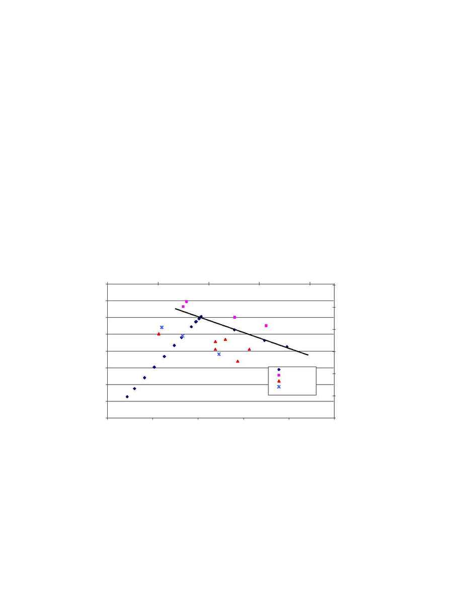
The graph below shows a standard operating diagram with liquid flow versus achievable vapor flow. The
MVGT data include the entire total reflux data along with the L/V run data. The Nye and Maxflow tray
data include the heavily loaded total reflux runs along with the available L/V data. Note that the bulk of
these data are for the 165 psia system while one set of data for the MVGT is the L/V data from the 100
psia system.
For the 165 psia operation, the trend line for the MVGT tray shows a clear advantage in hydraulic
capacity over both the Nye and Maxflow trays. The MVGT downcomer showed excellent capacity with
liquid loads in excess of 17 gpm/inch of weir.
The MVGT data for the 100 psia system show increased capacity over the 165 psia data, as would be
expected. The trend of the 100 psia and 165 psia operating lines are very similar. The L/V data from the
100 psia system also show very high vapor capacities at reduced liquid rates. It was not possible to obtain
the reduced liquid rate (L/V < 1) data for the MVGT tray at 165 psia because the tray capacity exceeded
the test unit boiler duty at these conditions.
Conclusions
The MVGT trays demonstrated excellent overall performance from both an efficiency and hydraulic
capacity standpoint. They provided the highest useful capacity of any tray tested at FRI in the Butane
system with efficiencies typically in excess of 100%. The tray also showed a turndown of 30%, which is
quite rare for a high performance tray.
Sulzer Chemtech would like to thank the FRI staff for their efforts during this testing.
HP Tray Operations Diagram
FRI Butane System
0.00
0.05
0.10
0.15
0.20
0.25
0.30
0.35
0.40
0
5
10
15
20
25
Weir Loading, gpm/inch
C
s
,
f
t
/
s
e
c
0.00
0.02
0.04
0.06
0.08
0.10
0.12
0
50
100
150
200
Weir Loading, m
3
/hr-m
C
s
,
m
/
s
e
c
MVGT 165
MVGT 100
Nye 165
MaxFlow 165
