HYDROCARBON PROCESSING / JULY 1999
For an alternate reactor type, choose it in the first
step and repeat the steps. Repeat the whole process for
all desired reactor types and operating modes (say with
recycle, multi-staging, reactor network and tempera-
ture programming, etc.) until the optimum of all pos-
sible designs is reached.
Using a general model, reactor performance is
obtained in the form of detailed axial profiles for all
major variables including temperature, pressure, com-
position, production rates, conversions, selectivities,
heat-generation rate, and other physical and hydrody-
namic conditions. The model outputs terminate with all
conditions at the reactor outlet.
Fig. 2 shows a schematic representation when apply-
ing a general reactor model in revamp and modernization
to meet market demands.
EXAMPLE 1--ACRYLONITRILE PRODUCTION
In this case study, a general model was used to eval-
uate the commercial performance projections of three
different reactor conf igurations in a typical petro-
chemical process. The reaction involved producing acry-
lonitrile from propylene by vapor-phase catalytic
ammoxidation. Preliminary reaction mechanism and
rate expressions as derived from a brief study of open
literature and are listed in Table 1. These values were
used for this example.
Approximate activation energies for the reactions
are also derived from the literature search. A general
reactor model is then applied to estimate the pre-expo-
nential factors of this 6-reaction
×
10-component sys-
tem. This is done by simulating the performance of a
typical commercial bubbling fluid-bed reactor. The pre-
exponential factors (k
01
*
k
06
*
, particle volume basis)
and the activation energies (E
1
*
E
6
*
) used are sum-
marized below:
k
01
*
(gmol/cm
3
/s) = 0.1710E+00
E
1
*
(cal/gmol) = 20,000
k
02
*
(gmol/cm
3
/s) = 0.1120E+00
E
2
*
(cal/gmol) = 20,000
k
03
*
(gmol/cm
3
/s) = 0.1630E+00
E
3
*
(cal/gmol) = 25,000
k
04
*
(gmol/cm
3
/s) = 0.5290E01
E
4
*
(cal/gmol) = 35,000
k
05
*
(gmol/cm
3
/s) = 0.1100E+00
E
5
*
(cal/gmol) = 35,000
k
06
*
(gmol/cm
3
/s) = 0.2150E+00
E
6
*
(cal/gmol) = 25,000
Using the general model, commercial projections for
a steam-cooled tubular fixed-bed reactor and a circu-
lating fluidized-bed reactor are made. Activity and
selectivity of the catalyst are assumed to be same for all
projections. Performance projections of the three reac-
tor configurations are summarized in Table 2.
This table immediately indicates that a bubbling fluid-
bed (BFB) reactor is perhaps the most attractive config-
uration between the three choices. It offers the highest
conversion and yield in a reasonable size reactor. The
BFB reactor also offers a significantly higher MTY (mass
time yield: tons of acrylonitrile production per ton of cat-
alyst) compared to the fixed-bed reactor due to opera-
tion at a much higher and uniform temperature level.
This is due to higher reaction rates at elevated temper-
Table 2. Performance projections of three reactor configurations for acrylonitrile production, capacity: 100 tpd**
Reactor
Inside
Height,
Temp.,
Propy-
Acrylo-
Acrylo-
MTY
1
,
Other key
type
dia.,
cm
°C
lene
nitrile
nitrile
(Mass
design/
cm
conver-
selecti-
yield, %
time
operating
sion, %
vity, %
yield)
features
Steam-
3.81
2
800
Feed 307
87.1
89.3
77.8
0.608
# of Tubes18,000
cooled
Peak 360
Catalyst particle
multi-
Exit 327
size
1
/
8
in.
tubular
Inlet gas velocity
fixed bed
45 cm/s
4
Bubbling
500
500
3
442
98.9
81.3
80.4
1.945
Catalyst particle
fluidized
size100 micron
bed
Inlet gas velocity
56 cm/s
4
Circulating
280
2,000
442
5
80.7
75.5
60.9
5.94
6
Catalyst particle
fluidized
size75 micron
bed
Inlet gas velocity
865 cm/s
4
Catalyst loading
51.54 kg/m
3
gas
** Assuming same feed composition as follows for all reactor types: C
3
H
6
8.3%, O
2
16.8%, NH
3
9.6%, H
2
O 1.5%
1
MTY: tons of acrylonitrile produced per ton of catalyst per day
2
Each tube
3
Dense bed height
4
Superficial velocity at inlet conditions
5
Feed temperature
6
Based on bed inventory only and does not include catalyst in the rest of circulation loop
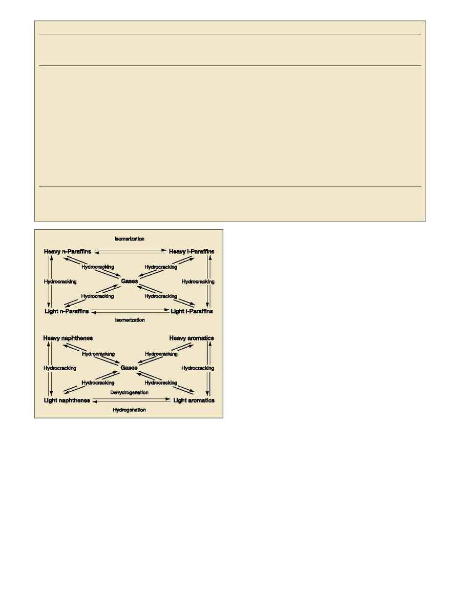
Fig. 3. Heavy hydrocarbons conversion reaction network.
