Kolmetz.com Thermo Paper Page 12

Van Laar Simulation Runs
Figure 4 shows a comparison of equilibrium data from simulator A, B and C using the
Van Laar model. The trends in this diagram are the same as seen in the NTRL diagram.
Simulators A and C give similar results while Simulator B varies like it did with the
NRTL method.
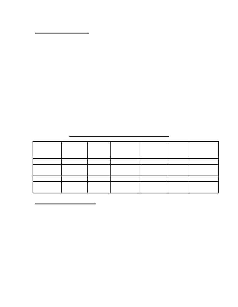
A comparison of the simulated results using the Van Laar model is given in Table 3.
The data in Table 3 shows good agreement between the plant data and the simulated
results. There is only a one-degree difference between the overhead temperature
measured in the plant and the temperature calculated in the simulation runs for simulator
A and B. Simulator C shows a two-degree difference in overhead temperature. There is
an approximate
± 3-degree difference in feed temperatures calculated for simulators A
and B with respect to the plant data. However, simulator C matched the feed temperature
data almost exactly. There is some slight variation in the calculated results for the EB
distillate composition and heavies' composition in the bottom. The results given by
simulator B did not match the EB composition in the distillate as well as the others.
Table 3. Comparison of Key Data using Van Laar
Ovhd
Temp
°F
Btm
Temp,
°F
Reboiler
Duty,
mmBtu/Hr
EB Comp.
Distillate
Wt%
Feed
Temp,
°F
Heavies in
the Bottom
Wt%
Plant Data
334 426
99.46 364
85.69
Simulator
A
333 425
2.80 99.46 362.1
86.27
Simulator B 333 422
2.72 99.12 367.9
86.28
Simulator
C
332 438
2.78 99.47 364.6
86.24
Equilibrium Curve Discussion
Figures 5 13 provide the equilibrium and operating curves for each of the individual
runs. There appears to be a pinch point at the top of the equilibrium profile in all of the
simulations. This pinch point is near the feed stage. The column does most of its
separation below the feed. Typically this type of pinch indicates that there is a
mislocated feed point. The feed point should be where the q-line intersects the
equilibrium curve. This is generally the rule in binary distillation. However, it is not
always true in multicomponent distillation. The optimum feed stage plot, Figure 1,
suggested the optimum feed stage is used in the simulation runs. (6)
Therefore, a pinch point appears in the equilibrium diagrams that can't be explained by
bad feed point location or system limitation. The pinch point tends to shift in simulator B
when the Van Laar model is used. In ternary and higher component systems, the
curvature in the operating lines will also sometimes cause curvature in the equilibrium
12
