P L A N N I N G I N F O R M A T I O N
All 200 Series undercounter units require the same basic
planning considerations before installing. Review the instal-
lation requirements for your particular unit. These charts
and illustrations provide planning information for all
Sub-Zero 200 Series models.
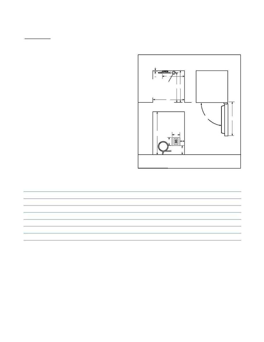
Refer to the Pre-Installation Specifications chart for impor-
tant information regarding area requirements, minimum
door clearance, electrical and plumbing placement.
The Model 315 can be ordered with or without a pump. If
you order the unit without a pump, you must install a drain.
Refer to illustration 1. The drain must be located in a two
inch area centered in the opening for the unit, 23-inches
back from the front door.
Model
245
249R
249RP
249FF
249FFI
315*
Finished Rough Opening (A)
24"
24"
24"
24"
24"
15
1
/
4
"
Finished Rough Opening (B)
34
1
/
2
"
34
1
/
2
"
34
1
/
2
"
34
1
/
2
"
34
1
/
2
"
34
1
/
2
"
Minimum Door Clearance at 90░ (C)
25
13
/
16
"
25
3
/
8
"
25
3
/
8
"
25
3
/
8
"
25
3
/
8
"
15
1
/
4
"
Minimum Height Required
34
1
/
4
"
34
1
/
4
"
34
1
/
4
"
34
1
/
4
"
34
1
/
4
"
33
3
/
4
"
Recommended Electrical Outlet Location (D)
1"
10
1
/
2
"
10
1
/
2
"
10
1
/
2
"
10
1
/
2
"
10
1
/
2
"
Recommended Electrical Outlet Location (E)
2"
8
1
/
2
"
8
1
/
2
"
2
1
/
2
"
2
1
/
2
"
2
1
/
2
"
Water Supply Location (F)
12"
N/A
N/A
N/A
18"
8"
*Pre-installation specifications for Model 315P are identical to the Model 315.
PRE-INSTALLATION SPECIFICATIONS
FRONT VIEW
B
LOCATE
ELECTRICAL
OUTLET WITHIN
SHADED AREA
E
A
7"
7"
24"
TOP VIEW
DOOR SWING CLEARANCE
90░
C
TOP VIEW
D
F
1
"
2
23"
LOCATE DRAIN
FOR MODEL 315 WITHIN
2" DIA. SHADED AREA,
23" BACK FROM THE
FRONT OF THE DOOR AND
CENTERED IN OPENING
*NOTE: MODEL 315 IS 19" DEEP
P R E - I N S T A L L A T I O N S P E C I F I C A T I O N S
2 0 0
S E R I E S
PRE-INSTALLATION
SPECIFICATIONS
Illus.1
