P L A N N I N G I N F O R M A T I O N
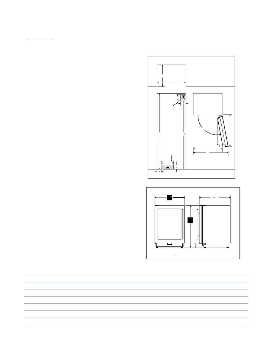
Review the installation requirements for your particular unit
in illustration 1 and the Pre-Installation Specifications chart.
They cover all the details you need to know about space
allocation and placement of electrical, whether the units
are framed, overlay, stainless steel or integrated.
The units must be installed to open a minimum of 90° or you
will have problems pulling the shelves out.
·
For corner installations, you need allow for a minimum
three-inch filler so the door can open to 90°. If you are using
some larger handle hardware, you will also need to take
that into account.
·
If installing a wine unit next to an existing Sub-Zero unit,
you may have to allow for a filler strip and possibly a heater
kit.
·
If you are connecting the unit to your home security
system, you must allow a minimum of 36 inches of the sys-
tem's wiring to be routed in the electrical area designated
for your respective model.
M O D E L 4 2 4 F S F R E E - S T A N D I N G
The new free-standing Model 424FS does not require any
panels or surrounding cabinetry. It has a beautiful stainless
steel exterior. Refer to illustration 2 for the Model 424FS
overall dimensions.
P R E - I N S T A L L A T I O N S P E C I F I C A T I O N S
PRE-INSTALLATION SPECIFICATIONS
MODEL 430
LOCATE ELECTRICAL
OUTLET WITHIN
SHADED AREA
FRONT VIEW
75
1
"
2
B
MODELS 424,427
AND 427R
LOCATE ELECTRICAL
OUTLET WITHIN
SHADED AREA
A
7"
6"
24"
TOP VIEW
DOOR SWING CLEARANCE
C
TOP VIEW
4
1
"
2
15
1
"
2
E
2
1
"
2
F
D
Model
424
427
427R
430
Finished Rough Opening (A)
24"
27"
27"
29
1
/
2
"
Finished Rough Opening (B)
34
1
/
2
"
80"
80"
83
3
/
4
"
Minimum Door Clearance (C)
25
3
/
8
"
25
1
/
2
"
25
1
/
2
"
30
1
/
8
"
Maximum Door Swing (D)
145°
105°
105°
130°
Minimum Clearance @ 90° Door Swing (E)
26"
28"
28"
33"
Minimum Clearance @ Maximum Door Swing (F)
44"
35"
35"
50"
Minimum Height Required
34
1
/
4
"
79
1
/
2
"
79
1
/
2
"
82
7
/
8
"
NOTE: Door swing clearances are based on stainless steel door and handle dimensions.
PRE-INSTALLATION
SPECIFICATIONS / ILLUSTRATIONS
4 0 0
S E R I E S
FRONT VIEW
SIDE VIEW
(CABINET DIMENSION)
*34
3
4
(883)
TOE SPACE
24
1
4
(616)
4
(102)
(625)
5
8
24
MODEL 424FS OVERALL DIMENSIONS
1
2
*
INCH
±
ADJUSTMENT IN LEVELING LEGS
Illus 1
Illus 2
