AD76PLPL.DOC
p. 3 of 14
b) Select
p_24x36.dwg
from the File Name area of the dialog box and select
OK
.
c)
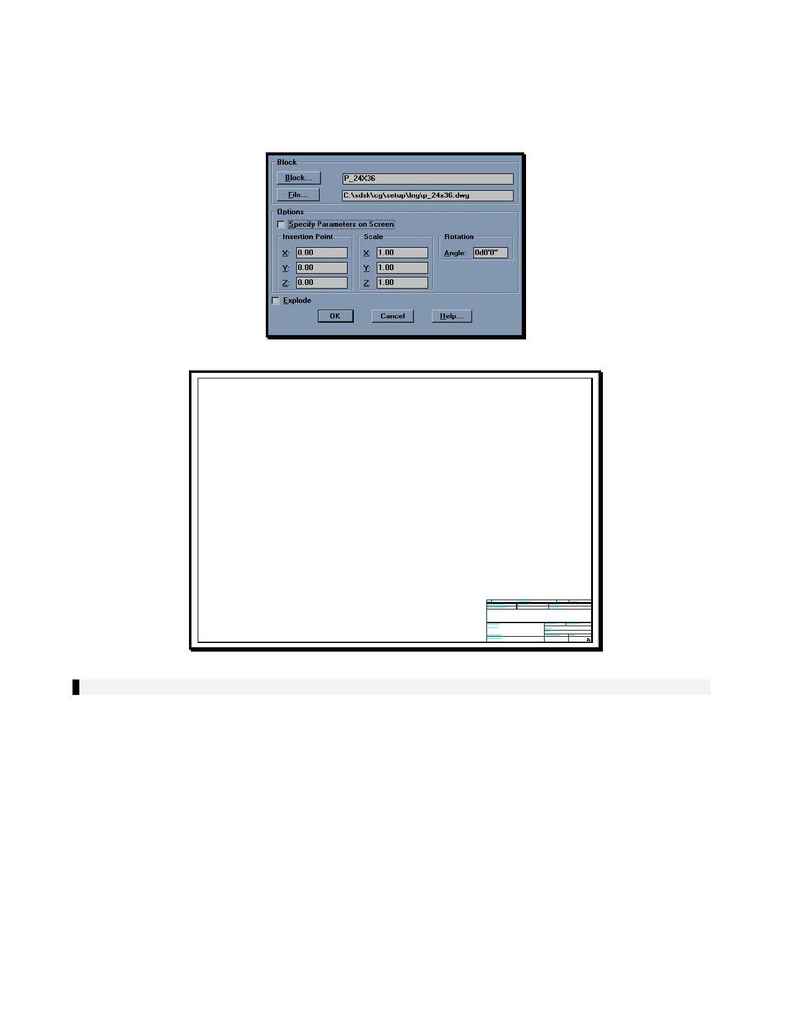
The Insert dialog box should now appear as shown in the following Figure
(
Figure II
). The Specify Parameters on Screen option should be toggled off
and the Explode option should be toggled off. Select
OK
.
Figure II
Figure III
NOTE: You are not allowed to have any blocks with attribute definitions within your sheet definition.
10. Create a temporary layer for layout of your viewports and frames.
a)
Type in `
layer
' at the command prompt and press
<return>
. In S8, you may type in `
_layer
'.
b)
Type in `
m
' for Make at the next prompt and press
<return>
.
c)
Type in `
temporary
' at the next prompt and press
<return>
.
d) Press
<return>
again to return to the drawing with the newly created layer set current.
11. Draw a rectangle to represent the location of the Northbound Plan View area. In
Figure IV
, this is
shown as `
A
'.
a)
Type in `
rectang
' at the command line and press
<return>
.
b)
At the First Corner prompt, type in `
3,14
' and press
<return>
.
c)
At the Other Corner prompt, type in '
34,22
' and press
<return>
.
12. Next, draw a rectangle to represent the Northbound Profile View area. Although this will not show on the
final plotted sheets, the profile view is essential to creating the sheet. In
Figure IV
, this is shown as
`
B
'.
a)
Type in `
rectang
' at the command line and press
<return>
.
