Raptor Software AD 76 PLPL Page 10

AD76PLPL.DOC
p. 10 of 14
50. Repeat these steps (48-49) for each sheet within that series.
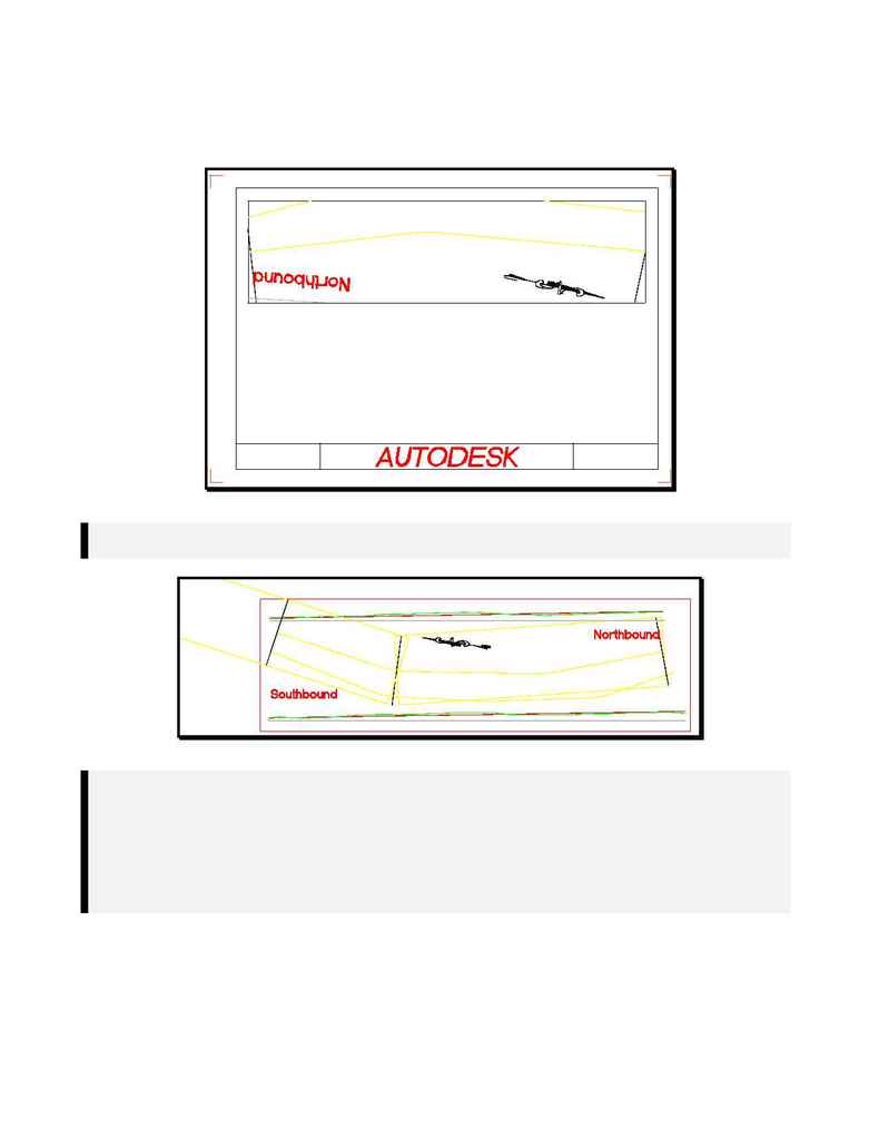
51. An example of an edited series sheet (
s001.dwg
) is shown in
Figure VI
.
Figure VI
Note: The Series Sheets will always be drawn from left to right. This can be a little confusing when
you have an alignment that is stationed from right to left. See
Figure VII
.
Figure VII
Note: In
Figure VII
, the rectangle on the right (that encompasses the "Northbound" and the North
Arrow) is drawn backwards and upside down in
Figure VI
. The output (
s001.dwg
) shown in
Figure VI
starts drawing from the left side of the viewport with the lowest station of the
alignment (the right side of the alignment shown in
Figure VII
).
To correct this problem, simply mirror the
<series name>_sheet_viewdef
rectangle about its
lengthwise midpoints and delete the old objects. Then, generate the series and follow the tech
note as you were previously.
52. Following the steps in the above note, you should have a first sheet (
s001.dwg
) that appears as shown
in
Figure VIII
.
