transition is very large. A radius corner follows the same principle as a bevel,
except that it uses an arc to round off a square corner.
The extra surfaces you create with beveled or radius corners also tend to
catch the light, making the object more interesting visually. Of course, it's
impractical to round off edges all the time, but adding even a few bevels to
an object can create the illusion that it's modeled at a much higher resolu-
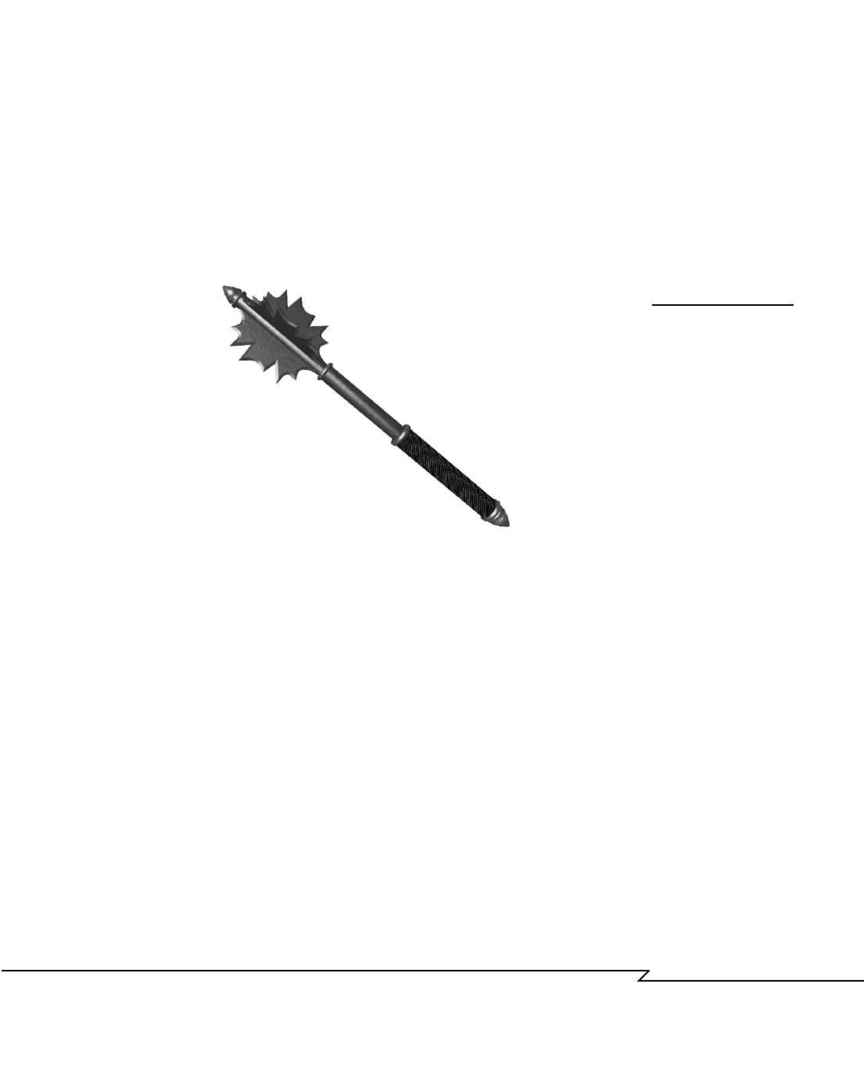
tion, and your results will look more professional (see Figure 4.4).
C
H A P T E R
4 : M
O D E L I N G
: B
E Y O N D
T H E
B
A S I C S
153
F
IGURE
4.4
The use of bevels on the
blades and cylindrical
trim rings make this
mace look as if it was
created at a higher
resolution than it really
was. Image by Mark
Giambruno/Mondo
Media for Zork:Nemesis
1996 Activision.
If your software offers extended primitives like the ones discussed in
Chapter 3, chances are good that they include beveled or radius cornered
cubes and cylinders. Using these primitives instead of the "squared off"
standard ones will make a mechanical model look more realistic and pro-
fessional with little extra effort.
Although some programs may have built-in automatic bevel tools or
options, many do not, leaving you to generate the bevel as part of a deform
modifier (which the next section explains), or to draw two cross-sections,
one slightly larger than the other, for skinning. Note that your software
may offer an outline tool that you can use to create the second cross-
section easily.
Another option for creating bevels is to leave an extra step or segment in the
loft or extrusion that you can manually edit by manipulating the faces or
vertices. The problem with creating bevels by scaling vertices or faces is
that unless the object is symmetrical, the scaling won't be even (see Figure
4.5). The only option you will probably have is to do a lot of tweaking to small
groups of vertices to even out the bevel.
04 2433_CH04 8/23/02 8:34 AM Page 153
