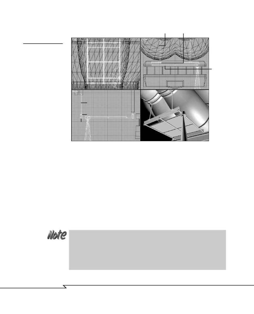
3. Create a clamp shape near the end of the beam and extrude it to be
wider than the I-beam (see Figure 4.38).
4. Create a 4-sided cylinder to connect the clamp to the ring above. Copy
the clamp and support and move it to the opposite end of the I-beam.
5. Copy the I-beam, clamps, and supports and move them directly under
the adjacent ring. Adjust the supports to reach.
6. Use 8-sided cylinders to create a framework of six horizontal supports
mounted to the I-beams.
7. Create a thin panel that covers the four large openings in the frame-
work. Name it CatGrd01.
3 D G
R A P H I C S
& A
N I M A T I O N
206
F
IGURE
4.37
Construct the catwalk
area using these views
or invent your own lay-
out. Consider adding
additional details like
railings, electrical con-
duits and equipment,
and so on.
Support
Clamp
Beam
Support
Clamp
Beam
The ship has a total of five searchlights with visible beams.This generic tutorial
presumes that your software doesn't offer volumetric lighting, so the visible
beams will be created with mesh and material settings. If your package does offer
volumetric lighting, you can skip step 10 and create a similar look by adding a vol-
umetric spotlight when doing the lighting tutorials instead.
04 2433_CH04 8/23/02 8:35 AM Page 206
