Complete the Thruster Assembly
Complete the thruster assembly by rotating the strut into position and cre-
ating the base and other details.
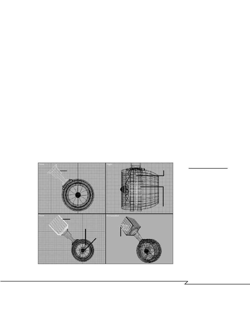
1. From the Front viewport, Unhide the thruster assembly and rotate it
counterclockwise 15░ so that the ThrMnt01 object is now at a 45░
angle. Move and rotate the ThrStr01 strut into position, making sure
it is centered over the thruster mount (see Figure 4.35a).
2. Create an engine for the thruster (ThrEng01), using a beveled cylin-
der. Create a support (ThrSup01) to hold the motor in place with a
simple cylinder (see Figure 4.35b).
3. Copy the mounting bracket ThrMnt01 from the thruster and rotate it
180░, positioning it as shown. Scale the bracket up until the circular
face is a bit larger than the end of the strut. Use vertex-level editing
to extend the end of the bracket. Name it ThrBas01 (see Figure 4.35c).
4. Create a cylinder and bevel one edge, positioning it so that it appears
to be a motor mounted to the bracket. Name it ThrMtr01 (see Figure
4.35d).
5. Save the file as B_THR18 and close it.
C
H A P T E R
4 : M
O D E L I N G
: B
E Y O N D
T H E
B
A S I C S
203
F
IGURE
4.35
Finishing the thruster
assembly: (a) Rotate
the thruster and strut
into position. (b) Add
an engine and support
to drive the propeller.
(c) Copy and modify
the thruster mount to
use as a base. (d) Add
a motor object on the
side of the base.
Strut
Base
Support
Motor
Engine
Engine
Support
(a)
(a)
(a)
(a)
04 2433_CH04 8/23/02 8:35 AM Page 203
