Displacement mapping can be used to solve a host of other modeling prob-
lems, from creating bas-relief (a style of sculpture where the subject projects
only slightly out of a flat background) to doing patch modeling-like mod-
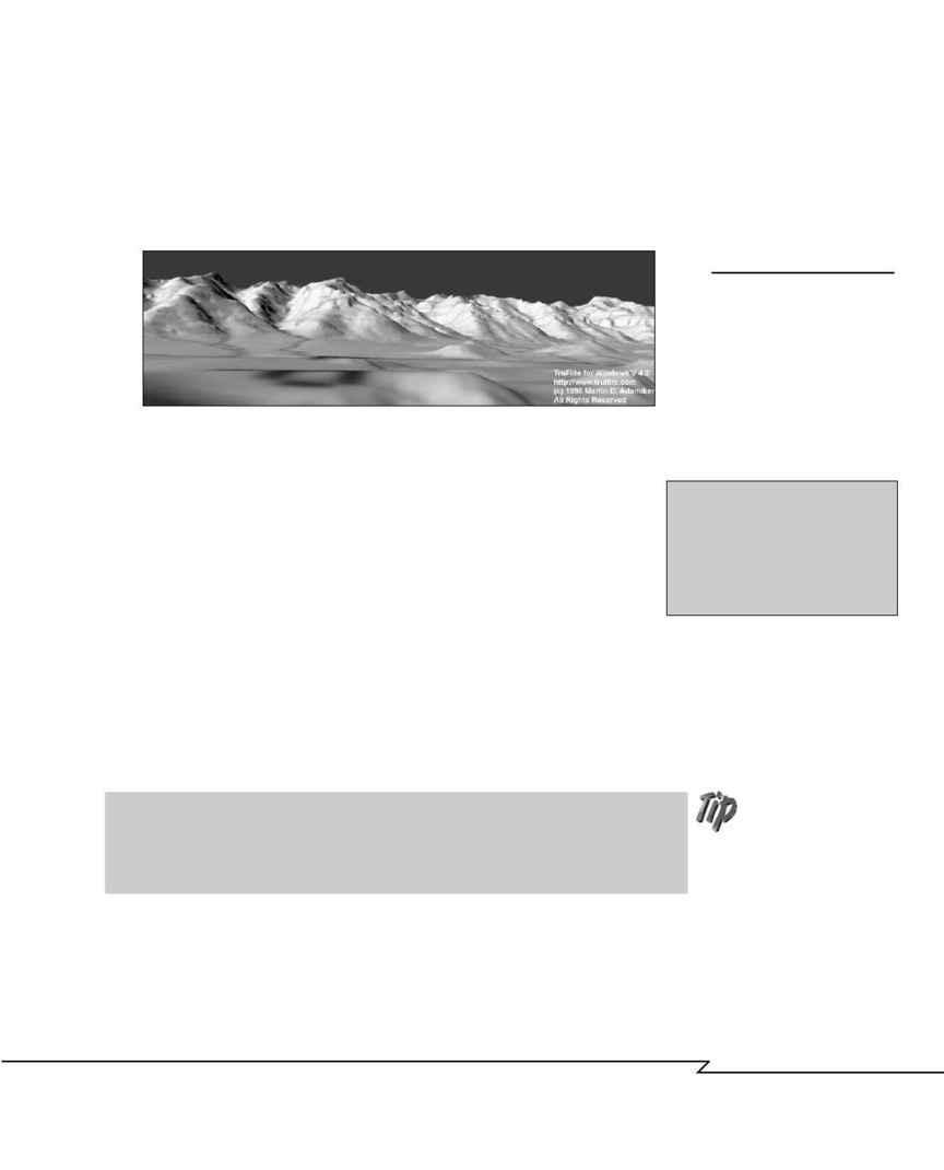
ifications to existing mesh. It is often used to create terrain models based on
grayscale imagery (see Figure 4.18).
C
H A P T E R
4 : M
O D E L I N G
: B
E Y O N D
T H E
B
A S I C S
167
F
IGURE
4.18
Terrain models are often cre-
ated with displacement map-
ping. For more accurate
results, some products, like
TruFlite, can generate mod-
els directly from geological
survey maps. Image
1996
Martin D. Adamiker.
One thing to keep in mind if you're planning to use displacement
mapping is that the base object should have a fairly substantial
number of faces in order to create subtle curves and detail. The
faces should also be triangles rather than quads to avoid planarity
problems. If you're planning to deform an extruded object, set the
cap style to grid, or use Boolean-cut grid shapes so that the objects
have a uniform pattern of faces and vertices for displacement.
The displacement level or displacement strength setting is the adjustment for
how much displacement occurs to the mesh and multiplies the grayscale
range provided by the displacement bitmap. Another factor that affects a
displacement operation is the mapping coordinates. For information on
how mapping coordinates work, see Chapter 6.
grid object
A flat poly-
gon, subdivided into trian-
gular or square faces.
definition
Using displacement to create terrain-style effects can be useful on a smaller scale
as well. For example, displacement mapping can be used at a low-strength level to
create rumpled sheets of paper from a simple flat rectangular grid object.
04 2433_CH04 8/23/02 8:34 AM Page 167
